
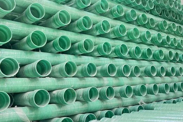
A GRP pipeline is designed for 50 years of pressure and chemistry, but it can lose the fight against groundwater in a single night. Buried pipe experiences an upward buoyant force whenever the water table stands above it, and an empty GRP line — light, thin-walled, air-filled — displaces several times its own weight in water. Every year, sections of pipeline float out of flooded trenches during construction or rise under pavements after design-stage assumptions about the water table turn out to be optimistic. Buoyancy control is not an optional refinement of buried GRP design; for lines in high groundwater it is a governing check that shapes cover depth, ballast, anchoring and construction sequencing. This guide works through the force calculation, a worked example at DN600, the three mitigation options, and the field rules that keep pipe in the trench where it was laid.
1. When Buried GRP Pipe Tries to Float
Flotation becomes a design issue whenever the groundwater level is, or can seasonally be, above the pipeline invert. Typical exposure scenarios: river and marsh crossings, flood plains, coastal reclamation, trench sections that stay open through a wet season, and — most commonly underestimated — ordinary urban alignments where dewatering during construction masks a high permanent water table that returns as soon as the pumps stop. The failure window is widest during installation, when the pipe is empty, the trench may be flooded, and the resisting weight of backfill has not yet been placed.
Two reference documents frame the design. ASTM D3839, the standard guide for underground installation of fiberglass pipe, covers trenching, bedding, embedment and deflection monitoring but explicitly excludes subaqueous installation guidance — so for submerged or high-groundwater conditions the engineer must assemble the buoyancy check from first principles and manuals such as AWWA M45. Utility design manuals such as WSSC's pipeline standard set out the accepted conservative procedure: analyse the pipeline empty, because the transported fluid is an additional safety margin that disappears during shutdown, maintenance or commissioning delays.
The worst case is always the empty pipe below the water table. Water inside adds about as much weight as the displaced water adds uplift, which is why water-filling during installation is such an effective construction measure — and why a line that is stable in service can still float out during a drained shutdown.
2. The Forces: Archimedes, the Empty-Pipe Assumption and the Safety Factor
The buoyant uplift per unit length on a fully submerged pipe is the weight of water displaced by its outer volume:
U = γw · π·Do²/4 (per metre)
where Do is the outer diameter including any coating, and γw is the unit weight of water (9.81 kN/m³ fresh; seawater and brackish water are heavier — WSSC's manual uses 62.4 lb/ft³ fresh vs 64.0 lb/ft³ seawater, a 2.6% step worth applying on coastal projects). The resisting forces are the pipe self-weight, the weight of any ballast, and — where the designer chooses to credit it — the weight of the soil cover above the pipe, computed with the submerged unit weight γ′ = γsat − γw because the soil below the water table is itself buoyant.
The check is a factor of safety: FS = total downward force / uplift. For vertical stability of empty pipelines, DNV-RP-F109 (offshore pipeline standard, section 3.2) applies a safety factor of 1.1 in the empty condition, and 1.1 has become the de-facto floor in onshore pipeline practice; project specifications for buried lines commonly demand 1.1–1.25, with higher values where liquefaction or uncontrolled groundwater rises are credible. Use the total outer diameter, the minimum wall thickness, and ignore nothing that floats — fittings, entrapped air and valve chambers all get their own check in section 8.
3. Worked Example: DN600 GRP Water Main at High Groundwater
Take a DN600 GRP pressure pipe with an outer diameter of 664 mm and a wall of 11.5 mm, buried with the crown 0.9 m deep in a trench where the water table stands 0.5 m below finished grade — so the pipe is fully submerged. Working in SI units per metre of pipe:
- Uplift on the empty pipe: U = 9.81 × π × 0.664²/4 = 3.40 kN/m
- GRP self-weight (laminate ≈1,900 kg/m³, mean diameter 0.6525 m): Wp = 0.44 kN/m
- Net uplift of the empty pipe: 2.96 kN/m — the pipe alone displaces nearly eight times its own weight
- Water-filled condition: internal water adds 9.81 × π × 0.641²/4 = 3.17 kN/m, so net = −0.21 kN/m: marginally stable, with almost no reserve
Two engineering conclusions fall straight out of these four numbers. First, for a thin-walled GRP pipe the water-fill trick nearly cancels buoyancy but does not create a comfortable margin — the −0.21 kN/m at DN600 is within the weight of a few litres of trapped air per metre of erasing it. Second, the empty-pipe net uplift of ~3 kN/m is what any permanent solution — soil cover or ballast — must resist with a 10% margin. The required resistance at FS = 1.1 is 1.1 × 3.40 = 3.74 kN/m.
| Quantity | Symbol | Value |
|---|---|---|
| Outer diameter (incl. coating) | Do | 0.664 m |
| Wall thickness | t | 0.0115 m |
| Uplift (empty, submerged) | U | 3.40 kN/m |
| Pipe self-weight | Wp | 0.44 kN/m |
| Required resistance at FS 1.1 | Rreq | 3.74 kN/m |
| Water-fill contribution | Ww | +3.17 kN/m |
| Net (water-filled) | — | −0.21 kN/m (sinks) |
4. Minimum Cover Without Ballast: The Soil-Prism Method
The simplest permanent fix is enough cover. The conservative "prism" method credits only the weight of the soil directly above the pipe (width = Do, height = cover above crown h), taken at the submerged unit weight. With saturated backfill at γsat = 19 kN/m³, γ′ = 19 − 9.81 = 9.19 kN/m³, the soil contribution is γ′ · Do · h and the safety factor is (Wp + γ′Doh)/U. For the DN600 example:
| Cover above crown | Soil weight (kN/m) | FS (empty pipe) |
|---|---|---|
| 0.4 m | 2.44 | 0.85 — floats |
| 0.6 m | 3.66 | 1.21 |
| 0.8 m | 4.88 | 1.57 |
| 1.0 m | 6.10 | 1.93 |
| 1.5 m | 9.15 | 2.82 |
| 2.0 m | 12.20 | 3.72 |
Inverting the inequality gives the minimum cover for FS = 1.1 without ballast:
hmin = (1.1·U − Wp) / (γ′·Do) = 3.30 / 6.07 ≈ 0.54 m above the crown.
Because uplift scales with D² while self-weight and the soil prism scale roughly with D, the required cover grows quickly with diameter — the design table below spans DN300 to DN1200. Three cautions on the method: it assumes the soil prism stays in place (not valid across a flowing riverbed or where scour occurs); it takes no credit for soil arching or shear (conservative in most soils, and rightly so); and loose, uncompacted backfill should not be credited at full γ′ until it has consolidated. Where the specification requires more conservatism, many designers apply FS values of 1.2–1.5 to the same calculation, which at DN600 pushes the minimum cover toward 0.7–0.8 m.
| Nominal DN | Do (m) | Wall (mm) | Uplift (kN/m) | Pipe weight (kN/m) | hmin @ FS 1.1 (m) | FS @ 1.0 m cover |
|---|---|---|---|---|---|---|
| 300 | 0.326 | 8 | 0.82 | 0.15 | 0.25 | 3.84 |
| 500 | 0.535 | 10 | 2.21 | 0.31 | 0.43 | 2.37 |
| 600 | 0.664 | 11.5 | 3.40 | 0.44 | 0.54 | 1.93 |
| 800 | 0.824 | 13.5 | 5.23 | 0.64 | 0.68 | 1.57 |
| 1000 | 1.020 | 15.5 | 8.02 | 0.91 | 0.84 | 1.28 |
| 1200 | 1.225 | 18 | 11.56 | 1.27 | 1.02 | 1.08 |
The DN1200 row is the headline: at one metre of cover the bare factor of safety is 1.08 — below the 1.1 floor — so large-diameter GRP in groundwater effectively always needs ballast or anchors unless the cover can be increased.
5. Option 1 — Concrete Weights and Set-On Saddles
Where cover cannot be increased, precast concrete weights ("set-on" saddles or river weights) are the classical answer. They add dead weight at discrete points, so the design unit is the weight spacing. A 1,000 kg saddle weighs 9.81 kN in air, but submerged it displaces water: the effective downward force is
Weff = Wair × (1 − ρw/ρconc) = 9.81 × (1 − 1,000/2,400) = 5.72 kN
Two scenarios show the range of demand. In the temporary construction condition — pipe laid in a flooded trench with no backfill yet — the deficit is the full required resistance minus the bare pipe: 3.74 − 0.44 = 3.30 kN/m, giving a spacing of 5.72/3.30 = 1.74 m, i.e. a 1,000 kg saddle every 1.7 m. In the permanent condition with 0.4 m of backfilled cover credited (soil adds 2.44 kN/m), the deficit falls to 0.86 kN/m and the same saddles can be spaced every 6.6 m. Checking the worst bay at 1.7 m: FS = (0.44×1.7 + 5.72)/(3.40×1.7) = 1.12 — just over the line, which is why the rounddown rule "specify the spacing, then verify the bay" matters; a sloppy contractor spacing at 2 m instead of 1.7 m drops the bay below FS 1.0.
- Fit every weight with a non-conductive liner or rubber pad — concrete bearing directly on the pipe wall creates point loads and can crack the laminate.
- Check the pipe for the concentrated reactions: short saddle spans are usually fine for GRP ring stiffness, but large-diameter thin-wall pipe may need wider bearing saddles.
- Strap or key the weights where backfilling could slide them along the pipe; a weight that migrates to mid-span between anchors is a point load you did not design.
- Continuous concrete coating is the alternative for short river crossings — uniform loading instead of point loads, at a cost premium that only pays off on short, high-exposure reaches.
6. Option 2 — Mechanical Anchors and Deadman Systems
Where ballast logistics are awkward (remote alignments, weight manufacturing lead times) or the uplift is extreme, the pipe can be tied down instead of weighed down. The common systems:
- Screw/helix anchors torqued into firm strata below the pipe, with a strap over the pipe barrel; capacity comes from soil shear at depth rather than mass, so they are compact to transport.
- Deadman or slab anchors: precast plates bedded in the trench bottom with tie rods over the pipe — effectively transferring uplift to the soil mass itself.
- Geotextile or fabric straps spread the tie-down load over a wider bearing arc of the pipe, avoiding the local shell stresses that narrow ratchet straps introduce.
Anchor design has its own two checks: the deep-soil capacity of the anchor itself (pull-out testing where the stratum is unproven), and the load distribution on the pipe shell — a tie-down applied on a narrow band must not exceed the local bearing or deflection limits of the laminate, which is why manufacturers publish strap-width and torque guidance for anchored installations. Anchors also survive the "no backfill yet" construction case naturally, which makes them attractive where a flooded trench will stay open for weeks.
7. Construction Sequencing: Water-Filling, Dewatering and the Pumps-Last Rule
Most floating-pipe incidents are sequencing failures, not calculation failures. The standard wet-trench procedure is a strict order of operations:
- Keep dewatering ahead of excavation: the trench bottom should be dewatered below bedding level — a commonly specified margin keeps groundwater at least ~300 mm below the invert during laying. EN 1610:2015, the European standard for drain and sewer construction, devotes its Annex A to dewatering methods (sumps, wellpoints, deep wells) and treats a stable, dry formation as a precondition of bedding Types 1–3.
- Water-fill the pipe during installation: filling the bore with water removes the dominant buoyancy term (at DN600, 3.17 kN/m of it) at trivial cost; purge entrapped air at high points, since air pockets restore uplift locally.
- Backfill before releasing the water table: place and compact the embedment and at least the flotation-critical cover before any planned shutdown of pumps. Stopping the pumps "because the pipe looks settled" is the single most common way installed pipe floats.
- Ballast the exposed reaches: wherever cover will be short (crossings, service stub-outs), install saddles or anchors as the pipe is laid, not as an afterthought from the finished surface.
One modern trap deserves its own warning: controlled low-strength material (CLSM / flowable fill) backfill is denser than water and, below the water table, produces more uplift than the water it replaces — a CLSM-encased pipe with no free water around it still needs anchoring for the 2× hydrostatic case. The same logic applies to any annular grouting around jacked or slip-lined GRP pipes; our earlier guide on GRP pipe jacking and sliplining covers the grouting side of that problem.
8. Fittings, Chambers and Entrapped Air
The pipe barrel is rarely the whole buoyancy problem. Each of the following floats on its own account and needs an individual check:
- Valve chambers and manholes: a 2 m deep, 1.2 m diameter chamber displaces roughly 22 kN of water and weighs far less empty; anti-flotation collars or base slabs are standard practice for deep chambers in high groundwater.
- Fittings and flanged assemblies: tees, bends and duckfoot blocks add displaced volume with little weight; concrete surround details should be part of the standard fitting drawings.
- Entrapped air: an air pocket at a high point reduces the internal water weight after filling and adds local uplift after submergence; air valves at summits and a pigging pass before final backfill are cheap insurance on lines intended to stay water-filled.
- Partial submergence: a pipeline whose water table varies seasonally must be checked with the maximum credible level, not the level observed during the site visit — flood events, irrigation seasons and municipal dewatering all move it.
A useful audit habit is to walk the alignment on the profile drawing and mark every point where the pipe or an appurtenance sits below the design maximum water table: those are the flotation checkpoints, and each one should carry its own FS calculation in the design file.
9. Field QC: Verifying That the Design Was Built
Buoyancy provisions fail silently if they are not inspected, so the acceptance plan should include them explicitly. ASTM D3839's installation framework already mandates deflection monitoring for buried fiberglass pipe — mandrel pulling or CCTV measurement — and deflection is a sensitive indirect indicator of embedment that was flooded or compacted under water. The buoyancy-specific additions:
- Record the water table during excavation (observation wells or standpipes give a defensible number, not a guess) and compare it with the design assumption before the pipe is laid.
- Verify saddle count, spacing and liner fit against the drawing before backfill — after backfill they are invisible, so photograph each installed weight or anchor.
- Confirm water-filling and purge on reaches designated to be filled, with fill level logged at the highest point.
- Sequence sign-off: a hold point on pump shutdown until the flotation-critical cover is placed and compacted — this is a single line in the ITP that prevents the most expensive failure mode.
- Post-construction monitoring on high-risk reaches: a level survey of the line at commissioning and after the first wet season detects early uplift movement while it is still a repair rather than a re-build.
- Tightness testing: EN 1610's leakage tests (air method L or water method W) close out the mechanical integrity question — a line that floated, strained its joints and then passed air testing was lucky, not compliant.
10. A Specification Checklist for Buoyancy-Critical GRP Lines
- Design maximum groundwater level stated on the drawings, with the data source and seasonal allowance.
- Flotation check on the empty pipe at FS ≥ 1.1 (DNV-RP-F109 §3.2 basis), higher where specified, using total outer diameter and minimum wall thickness.
- Soil credit (if any) defined: prism method, submerged unit weight, and the compaction state at which it applies.
- Ballast solution fixed per reach: saddle weight, liner detail and maximum spacing — or anchor type, capacity test requirement and strap width.
- Water-filling requirement, air purge points and pump-shutdown hold point written into the installation method statement and ITP.
- Chambers and fittings checked individually for flotation with their own countermeasure details.
- Deflection monitoring and EN 1610 tightness testing in the acceptance plan, plus a post-wet-season level survey on high-risk reaches.
GRP's corrosion immunity is what puts it in the ground in the first place — but in high groundwater the material's lightness is the enemy, and the projects that treat flotation as a governing load case are the ones that never dig up a floating main.
Uplift scales with the square of the diameter; the pipe's own weight does not. That single fact is why DN1000+ GRP lines in groundwater almost never meet FS 1.1 on cover alone — and why ballast and anchors belong in the standard drawings, not the variation orders.
Engineer Your GRP Pipeline for the Water Table You Have
HuanGang supplies filament-wound GRP/FRP pipes and fittings for water, wastewater and industrial service, including pressure and gravity lines for high-groundwater installations. Send us your diameters, pressure class, alignment profile and groundwater data, and we will support the buoyancy design, ballast detailing and jointing plan for the project.
Related reading: GRP Pipe Bedding, Backfill and Ring Deflection · Thrust and Anchor Block Design for Buried GRP Pipelines · FRP Pipe Installation and Pressure Testing · Hydrotest Water Quality for FRP and GRP · FRP Pipe Support Spacing and Hanger Design · Product pages: FRP water pipe · Filament-wound FRP/GRP process pipes · FRP pressure pipe
Need help selecting FRP products?
Our engineers answer technical questions free of charge.
Ask an Engineer on WhatsApp