
A 12 m diameter storage tank cannot leave a factory. It is wider than a motorway lane, taller than a container and heavier than most site cranes will lift at radius. The moment a project crosses roughly 4 m in diameter, the manufacturing method stops being a production decision and becomes a logistics one: either the tank is built in sections and joined on site, or the winding machine travels to the tank. On-site filament winding — sometimes called field winding or site winding — is the second route, and it has become the default for large chemical, water and effluent tanks in Asia, the Middle East and Latin America. This guide covers the equipment, the mandrel strategy, the site conditions that decide whether the laminate cures properly, the winding geometry and thickness build, the sectional joints, and the field quality control that has to produce evidence rather than opinions.
1. Why the Transport Envelope Decides the Manufacturing Method
Before any laminate is designed, check what can physically reach the site. The limits are hard numbers, not preferences, and they differ by mode:
| Envelope | Usable dimensions | What it rules out |
|---|---|---|
| 40 ft high-cube container (internal) | 12.03 m × 2.35 m × 2.69 m | Any shell over about 2.3 m diameter, any tank longer than 12 m |
| 40 ft flat rack (deck) | 12.0 m × 2.44 m, no roof | Diameter above roughly 2.4 m without overhang |
| Standard road trailer, no permit | 13.6 m bed, 2.55 m width | Anything wider than 2.55 m |
| Wide-load permit (typical) | 3.5–4.5 m wide, escorts and route survey above 3.5 m | Tanks above about 4.3 m diameter become uneconomic |
| Rail clearance, typical | About 3.2 m width | Large tanks entirely |
The practical break-even sits near 4.0 m. Below that, a shop-wound tank is cheaper, better controlled and easier to inspect, and it arrives with factory test records. Above it, freight stops scaling linearly: a 6 m diameter tank needs a route survey, police escorts, temporary road widening, tree trimming and a crane at both ends, and the freight quote often exceeds the laminate cost. A 12 m diameter tank has no legal road route at all in most countries.
There is a middle route — shop-wound sections bolted or laminated together on site — and it is legitimate up to perhaps 8 m diameter. But every joint is a discontinuity, and a horizontal joint at mid-height sits exactly where the hoop stress is highest. Site winding removes that compromise: the shell is continuous from the base knuckle to the top flange, wound in one campaign, with only the vertical manway and nozzle cut-outs interrupting the laminate.
2. What On-Site Winding Equipment Actually Looks Like
Site winders come in two families, and the choice between them fixes the tank geometry for the rest of the project.
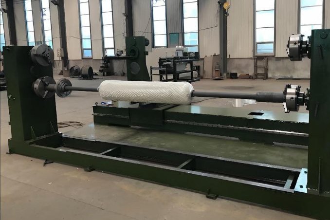
Horizontal site winders keep the mandrel axis horizontal, driving the mandrel from a headstock with a tailstock support, and traverse a carriage along a track. They are the direct descendants of shop pipe and tank machines, scaled up and built in bolt-together modules so they fit in containers. Published specifications for this class typically quote diameters from DN4000 to DN15000, a maximum wound length of 12 m, roving sheet widths up to 1680 mm, torque in the region of 68,000 N·m, installed power around 19 kW and output of 500–550 kg/h of laminate.
Vertical site winders rotate a horizontal table on a hydraulic or slewing-ring bearing while a column-mounted carriage climbs and descends. The tank is wound standing up, on its own base, which is exactly how it will be installed. Published specifications for the large class quote 4 m to 25 m diameter, a maximum wound section height of about 6 m per stage, winding angles from 60° to 90° from the axis, mandrel speed around 4.6 rpm, roughly 70 roving ends, about 500 kg/h output and an installed footprint of 35 m × 35 m. Power for the largest machines is in the 55 kW range, plus a compressed-air supply of about 1.4 m³/h at 7 bar for the tensioner and resin system.
| Parameter | Horizontal site winder | Vertical site winder |
|---|---|---|
| Typical diameter range | DN4000–DN15000 | 4–25 m |
| Maximum wound length / height per stage | 12 m | About 6 m per stage; taller tanks in stages |
| Winding angle (from axis) | 45°–90° | 60°–90° |
| Mandrel speed | Set by surface speed, typically 1–3 rpm at large diameter | Up to about 4.6 rpm |
| Output | 500–550 kg/h | About 500 kg/h |
| Site footprint | Track length plus 10 m each end | About 35 m × 35 m |
| Best suited to | Long tanks, silos, pipe, tanks up to about 12 m diameter | Tanks 8 m and above, and anything over 12 m |
The machine is the cheap part of the decision. The expensive parts are the foundation it stands on, the enclosure that keeps dew off the laminate, and the seven to ten days of skilled labour that follow the last revolution.
3. Choosing the Mandrel: Steel, Sectional or Liner-as-Mandrel
Every winding job needs a surface to wind onto, and on site that surface is the hardest thing to get right. Three options dominate.
- Sectional steel mandrel. Bolted ring segments with a slight taper, assembled on the base plate, stripped and craned out through the manway. Accurate and reusable, but the tooling cost for a 12 m diameter mandrel is a five-figure sum in itself, and the crane lift to remove it can be the heaviest lift on the project.
- Liner-as-mandrel. The corrosion barrier — surface veil, two or more chopped-strand mat layers, resin-rich — is fabricated first on a temporary support frame or directly on the tank base, cured, then wound over. The liner stays in the finished tank as the corrosion barrier and the structural laminate bonds to its abraded, resin-rich outer surface. This is the standard approach for large site-wound chemical tanks because it eliminates both the tooling and the extraction lift.
- Lost or expendable mandrel. Sand, plaster, soluble plaster or a cardboard former that is broken out afterwards. Used for odd geometries and small quantities; it leaves a rougher inner surface and is rarely acceptable for a corrosion barrier that will be inspected to ASTM D2563.
With the liner-as-mandrel route, three details decide the result. First, the liner must be supported so that it does not deflect under winding tension — a 12 m diameter liner with 2.5 mm walls is a flexible shell, and 200 N of roving tension per band will ovalise it if the temporary frame is undersized. Second, the liner's outer surface must be freshly abraded and solvent-wiped within the working window; a cured, glossy liner surface is a release layer, not a bonding surface. Third, the liner must be dimensionally correct before winding starts, because nothing later can bring an oval shell back to round.
4. Site Works: Foundation, Footprint and Utilities
The tank foundation is poured first and used as the winding base, which is efficient but unforgiving: any error in the base is locked into the tank. A site-wound tank needs a level, continuously supported base — typically a ringwall or an insulated concrete pad with a flatness of a few millimetres over 3 m, and anchor provisions cast in before the pour, not drilled afterwards.
Layout the site against the machine, not the tank. For a vertical machine in the 20 m class, budget 35 m × 35 m of clear, hard-standing ground: the machine footprint, the roving creel, the resin station, the laydown area for the next stage's liner, and the crane set-down zone all compete for the same square metres. Add:
- Power: 55 kW at the machine, plus 20 kW of lighting, heaters and tools, on a stable supply — voltage sag mid-pass changes the band spacing.
- Compressed air: clean and dry, about 1.4 m³/h at 7 bar for tensioners and resin pumps; oil carry-over contaminates resin.
- Water and drainage: for hydrotest later, and for cleaning. A 12 m × 9 m tank holds over 1,000 m³.
- Access for a 40 t crane and for the resin deliveries, which arrive as 220 kg drums on a flatbed.
- A bunded, shaded resin store with the drums off the ground — styrene drums sitting in sun on hot concrete are a delivery of gel particles waiting to happen.
5. Temporary Enclosure and the Dew Point Rule
Winding outdoors is done, and it is done badly more often than well. Resin and glass do not care about the view; they care about substrate temperature, humidity, dust and wind.
The governing rule is the one used in protective coatings: the substrate must be at least 3 K above the dew point during lamination (ISO 8502-4). Below that margin, moisture condenses on the liner or on the previous layer, and the result is a bond line with a film of water in it — invisible at the time, and a disbond or blister six months later. The dew point moves fast with weather:
| Ambient | Relative humidity | Dew point | Minimum substrate temperature (3 K margin) |
|---|---|---|---|
| 15 °C | 60% | 7.3 °C | 10.3 °C |
| 25 °C | 70% | 19.1 °C | 22.1 °C |
| 30 °C | 80% | 26.2 °C | 29.2 °C |
| 35 °C | 85% | 32.1 °C | 35.1 °C |
Read the last row again: at 35 °C and 85% RH, a steel or concrete substrate has to be above 35 °C to be safe, which is essentially impossible without heating or dehumidification. This is why tropical projects schedule winding for the middle of the day, or erect a dehumidified enclosure, or both. A simple scaffold-frame shelter with tarpaulins and two 5 kW heaters will hold a 12 m tank zone at 25–28 °C and 60% RH for the cost of a few days of site labour — far less than a reline.
Enclosure also controls three other variables that quietly ruin laminates:
- Dust. Wind-borne grit lands between layers and becomes a void. Overhead tarps and a swept, dampened floor are the minimum.
- Direct sun on the resin bath. A black bath in sun reaches 50 °C, the resin gel time halves, and the bath starts to string. Cover it and monitor bath temperature.
- Wind across the wet laminate. Moving air strips styrene from the surface, which inhibits cure and leaves a tacky skin. Below about 5 m/s winding can continue; above that, the enclosure is doing structural work.
6. Winding Pattern, Glass Content and Stepped Thickness
Now the part that is engineering rather than logistics. Take a worked example: a vertical tank 12 m diameter, 9 m of liquid height, contents at specific gravity 1.2, corrosion barrier 2.5 mm excluded from the structural calculation.
Bottom-head pressure is γ·h = 9,810 × 1.2 × 9 = 105.9 kPa. Using the thin-shell hoop relation t = p·D/(2σ), the required structural thickness depends entirely on the allowable stress. At 30 MPa it is 21.2 mm; at 25 MPa it is 25.4 mm. Which is right? For filament-wound tanks the governing criterion is usually strain, not stress: ASTM D3299 works to an allowable laminate strain of 0.0010 in/in at 21 °C. With a hoop modulus of 25 GPa that is 25 MPa — and 25.4 mm at the bottom course. That 4 mm difference is not academic: on 339 m² of shell it is about 1.4 m³ of laminate.
Good practice does not wind the whole shell at the bottom thickness. Thickness is stepped in courses, each sized to the head at its own mid-height:
| Course (from top) | Head at mid-height | Pressure | Structural thickness |
|---|---|---|---|
| 1 | 8.1 m | 95.4 kPa | 23 mm |
| 2 | 6.3 m | 74.2 kPa | 18 mm |
| 3 | 4.5 m | 53.0 kPa | 13 mm |
| 4 | 2.7 m | 31.8 kPa | 8 mm |
| 5 | 0.9 m | 10.6 kPa | 8 mm (minimum) |
Note the floor at 8 mm: below a certain thickness the laminate stops being windable and handleable, and ASTM D3299 sets a minimum structural thickness of 3/16 in (4.76 mm) for exactly this reason. In practice most fabricators will not go below 6–8 mm on a large shell because the winding pattern needs a minimum number of layers to build evenly. Also note that D3299 covers atmospheric tanks up to 82 °C service; above that, elevated-temperature design data from the resin supplier is required.
The glass content target for the structural layer is 60–65% by weight for filament winding, with the corrosion barrier at roughly 25–30%. Those numbers are set by the resin-to-glass balance the process can achieve, not by preference: below 60% glass the laminate is resin-rich and cracks under strain; above about 70% the roving is starved and voids appear between bands.
Adding the courses up gives about 4.75 m³ of structural shell laminate, 2.94 m³ of bottom, and 1.13 m³ of barrier — roughly 8.8 m³ of laminate at 1.85 t/m³, or 16.3 t. At 65% glass that is 10.6 t of glass and 5.7 t of resin. At 500 kg/h of machine output, net winding time is about 33 hours — and that is the smallest part of the schedule.
Winding geometry is where supervisors and designers most often talk past each other. For a helical pass at angle α from the axis, with a band width w measured perpendicular to the fibres, the axial advance per revolution is s = w / sin α. With a 40 mm band:
| Winding angle from axis | Axial advance per revolution | Revolutions for a 9 m pass | Time at 4.6 rpm |
|---|---|---|---|
| 45° | 56.6 mm | 159 | 35 min |
| 55° | 48.8 mm | 184 | 40 min |
| 60° | 46.2 mm | 195 | 42 min |
| 75° | 41.4 mm | 217 | 47 min |
| 85° | 40.2 mm | 224 | 49 min |
The near-vertical angles are hoop layers, the ones that carry the pressure; helical layers at around 55° carry the axial and bending loads and are what resist wind and seismic. A typical build alternates: two hoop layers, one helical, repeated, with the helical angle chosen so that the pattern closes on itself at the manway cut-out rather than crossing it.
7. Sectional Shells: Joints, Tapers and Secondary Bonding
Vertical machines wind about 6 m of height per stage. A 9 m tank is therefore two stages: the lower 6 m wound on the mandrel or liner, the upper 3 m wound on a second liner that is then joined to the first. The joint is a secondary bond, and secondary bonds are where site-wound tanks fail.
The joint geometry that works is a tapered lap: both shell ends are ground to a 1:4 taper over at least 100 mm, the surfaces are abraded to expose fresh laminate, solvent-wiped and allowed to dry, and the joint is rebuilt with alternating chopped-strand mat and woven roving to match the parent laminate schedule. Five rules govern the detail:
- Never bond to a gel coat or a release-agent-contaminated surface. The taper must cut through to structural laminate on both sides.
- Match the schedule, do not just add thickness. A joint twice as thick but all mat has lower hoop strength than the parent.
- Control exotherm. A 100 mm wide, 360° joint on a 12 m tank is a lot of resin in one pour; build it in two or three passes so the peak exotherm does not crack the parent laminate.
- Stagger the passes. Joint overlaps should step around the circumference so no two butt ends align.
- Coupon the joint. Wind a flat test panel with the same schedule alongside the tank and cut specimens from it, so the joint has a number attached to it rather than a signature.
8. Field Quality Control That Produces Evidence
In a shop, quality control is a routine. On site it is a project, and it has to generate records that a client's inspector will accept. The minimum programme for a site-wound tank:
| Check | Method | Frequency | Acceptance |
|---|---|---|---|
| Cure / hardness | Barcol impressor, ASTM D2583 | Per course, at least 5 readings per 10 m² | Not less than 90% of the resin supplier's minimum |
| Glass content | Burn-off, ASTM D2584 | One coupon per stage and per joint type | 60–65% structural; 25–30% barrier |
| Thickness | Ultrasonic gauge or calibrated caliper on coupons | Per course, 8 points minimum | Not less than design; typically 0/+20% |
| Visual defects | ASTM D2563 classification | 100% of accessible surface | No blister, delamination, dry spot or crack; others per agreed grade |
| Dimensions | Tape, plumb-bob or total station | After each stage | Diameter ±0.5%; verticality ≤ H/500; nozzle positions ±10 mm |
| Joint integrity | Visual plus tap test, coupon tests | Every joint, 100% | No hollow sound; coupon strength ≥ parent laminate |
| Barrier continuity | High-voltage spark test on conductive-lined tanks, or visual | 100% where specified | No holiday |
Two of these are routinely skipped and should not be. The Barcol reading must be taken on the surface that will be exposed to the chemical, after post-cure, not on a convenient outside patch. And the coupon has to be wound with the same roving, same resin batch and same pattern as the tank; a coupon from the shop's standard panel proves nothing about site conditions.
9. Hydrotest, Settlement and Handover
A site-wound tank is tested where it stands, which means the test is also a test of the foundation. For the 12 m × 9 m example, geometric volume is about 1,018 m³; filling at 20 m³/h takes 51 hours, at 40 m³/h about 25 hours. Do not rush it. Water loading at full height applies roughly 1,000 t to the base, and settlement that happens after handover becomes a nozzle alignment problem.
The sequence that works:
- Fill in four stages — 25%, 50%, 75%, 100% of design level — holding 2–4 hours at each stage.
- Take settlement readings at four points on the base ring at each stage; differential settlement is the number that matters, not absolute settlement.
- Inspect every joint, nozzle and the base knuckle at each stage, in daylight, from inside and outside.
- Hold at full level for at least 24 hours; record any weep, damp patch or level drop.
- Drain, then inspect the barrier for blistering or whitening — the first fill is the harshest thing a new barrier sees.
Water quality matters more than most site teams expect: chlorinated mains water at 50 °C is a different fluid from cold well water, and chloride in test water can leave a barrier with a residual osmotic driving force. Use clean water, keep the temperature below the resin's heat distortion margin, and dry the tank before service if the contents are non-aqueous.
10. Cost and Schedule Comparison: Shop vs Site
The commercial case is rarely decided on laminate cost, because the laminate is similar either way. It is decided on the cost of moving a large object.
| Cost line | Shop-wound, delivered | Site-wound |
|---|---|---|
| Laminate and materials | Baseline | +5–10% (site waste, small-batch resin, weather losses) |
| Freight | Oversize permit, escorts, route survey, crane both ends | Machine in containers, standard freight |
| Site works | Foundation only | Foundation + hardstanding + enclosure + power + water |
| Labour | Factory rates | Site rates, plus travel and accommodation for the crew |
| Quality control | Factory QC, third-party witness at the works | Site QC, more inspector hours, more records |
| Schedule | 6–10 weeks in the works, then shipping | 4–8 weeks on site, weather-dependent |
| Risk | Transport damage, joint quality in sections | Weather, site contamination, labour quality |
The decision rules that hold up in practice:
- Below 4 m diameter, buy shop-wound. The site premium is all cost and no benefit.
- 4–8 m, compare honestly: a sectional shop-wound tank with one laminated joint is often cheaper than mobilising a winder, and it is easier to inspect.
- Above 8 m, site winding wins on both cost and integrity. Above 12 m, it is the only option.
- Whatever the size, put the winder's mobilisation, the enclosure and the site QC programme in the same budget line as the freight — otherwise the comparison is fiction.
Plan Your Site-Wound Tank With Us
Whether the tank leaves our works in one piece or is wound on your foundation, the design has to be settled before the first drum of resin arrives. Send us the diameter, liquid height, specific gravity, design temperature, chemical list and site location, and we will come back with the laminate schedule, the winding angle set, the joint detail and the field QC plan. Our 4-axis filament winding machines and CNC winding lines for tanks and pipes cover both shop and site configurations, and our tank team can quote the vessel itself if you would rather buy the finished article.
Related reading: FRP Filament Winding Machine Buyer's Guide · Filament Winding Angle Design for Pipes and Tanks · Filament Winding Mandrel Design, Taper and Extraction · FRP Tank Hydrotest and First Fill · Vacuum and External Pressure Design for FRP Tanks · Product pages: CNC filament winding production line · FRP vertical storage tank
Need help selecting FRP products?
Our engineers answer technical questions free of charge.
Ask an Engineer on WhatsApp