
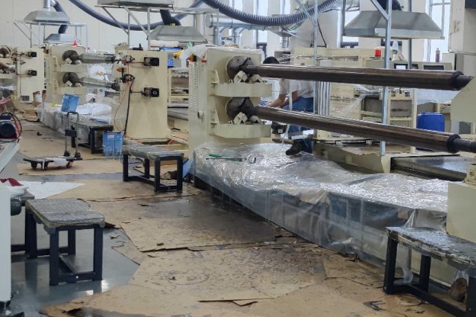
Every filament winding enquiry eventually arrives at the mandrel, and that is usually where the project stops being simple. The machine can be specified from a catalogue: axes, payout eye, tensioner, control system. The mandrel cannot, because it has to survive three incompatible loads at once, and then it has to let go of the part it has just made. A ten millimetre hoop layer wound at ordinary commercial tension puts about three bar of pressure on the inside of the mandrel and grips it with a force measured in tonnes. This guide works through what that means: the pressure the winding applies, why a thin mandrel implodes rather than yields, how wall thickness and internal diaphragms trade against each other, why draft angle is a much weaker release tool than most suppliers suggest, and the cure-cycle trick that actually gets the part off.
1. The Mandrel Is the Most Expensive Part of the Winding Cell
On a tank or pipe cell, the machine is bought once and amortised over a decade of production. The mandrel set is bought once, abused continuously, and replaced every few years when its surface is no longer round enough or its taper has been scored away. For large tanks the mandrel set can cost as much as the machine itself, because a single tank mandrel is a tonne or more of fabricated steel that has to be machined on the outside, stress relieved, and inspected for roundness.
The design problem has three parts, and they pull in different directions:
- The mandrel has to be stiff enough that the part comes out round and straight, which pushes towards thick walls and large diameters.
- The mandrel has to be stable under the winding pressure, which pushes towards thick walls, internal stiffening or both.
- The mandrel has to release the part, which pushes towards collapsible construction, sacrificial materials or at least a generous taper, and every one of those costs roundness or money.
A design that satisfies the first two and ignores the third is the most common failure in a new cell: the part is perfect and it will not come off.
2. The Mandrel Families and What Each One Costs
There are four practical families. They are not interchangeable, and the choice is driven by the part's aspect ratio and by whether the part has a closed or domed end.
| Family | How it releases | Roundness | Best for | Cost of ownership |
|---|---|---|---|---|
| Single-piece tapered steel | Axial pull, whole part slides off the small end | Excellent, 0.5 mm on diameter achievable | Pipes, poles, tubes, short cylinders | Low capital, high extraction force, surface wears |
| Collapsible or segmented | Segments drawn inward, part lifts off radially | Good, typically 1 to 2 mm on diameter | Tanks with domed ends, large diameter cylinders | High capital, mechanisms need maintenance |
| Sacrificial | Part stays, mandrel is dissolved, melted or broken out | Excellent, it is the same every time | Complex closed shapes, prototypes, small batch | Consumable cost per part, waste disposal |
| Expandable or inflatable | Bladder deflates or segment pack contracts | Moderate, dependent on internal pressure | Thin-wall tanks, large diameter low pressure parts | Low weight, but pressure integrity is critical |
A collapsible mandrel is not simply a mandrel with a joint in it. The segments need a central shaft and a locking mechanism, they need a taper or a wedge so they come apart, and they need enough wall thickness of their own that they do not distort under the winding pressure before the part cures. The gap between segments becomes a witness mark on the inside of the part, which is acceptable for a buried tank and unacceptable for a pressure pipe.
3. What the Winding Tension Does to the Mandrel
The starting point is the hoop force that one pass of the band imposes. Take a band of 20 rovings of 2,400 tex glass, each at 30 N of tension, laid 100 mm wide. The band carries 600 N and it is 0.1 m wide, so the hoop force per unit of axial width is 6,000 N per metre, per layer. At 55 per cent fibre volume the same band is 0.246 mm thick cured, so a 10 mm hoop laminate is 40 passes.
The pressure on the mandrel is the summed hoop force divided by the radius. This is the thin-shell relation written the other way round:
p = H / r, where H is the total hoop force per unit axial length in newtons per metre. Equivalently, H equals the hoop stress in the finished laminate multiplied by its thickness, so the pressure can be derived either from the winding schedule or from the laminate design, and the two must agree.
| Case | Mandrel OD | Length | Hoop wall | Passes | Hoop force H | Pressure on mandrel |
|---|---|---|---|---|---|---|
| Tank DN1600 | 1,600 mm | 3.0 m | 10 mm | 40 | 240,000 N/m | 300 kPa |
| Pipe DN600 | 600 mm | 6.0 m | 6 mm | 24 | 144,000 N/m | 480 kPa |
| Pole, 300 mm base | 300 mm | 12.0 m | 5 mm | 20 | 60,000 N/m | 400 kPa |
| Tank DN2400 | 2,400 mm | 4.0 m | 14 mm | 56 | 336,000 N/m | 280 kPa |
The absolute value is the surprise for most people who have not run the numbers: a few hundred kilopascals, which is three or four bar, sitting inside the mandrel for the whole of the winding cycle. It is a real pressure, it acts continuously, and it is applied from the outside in.
4. Strength Passes Easily, and That Is the Trap
Check the mandrel as a pressure vessel and it looks reassuring. The membrane hoop stress in the mandrel is p times diameter over twice the thickness.
| Mandrel | Pressure | Wall | Membrane stress | Fraction of yield |
|---|---|---|---|---|
| Tank DN1600 | 300 kPa | 3 mm | 80.0 MPa | 32 per cent |
| Tank DN1600 | 300 kPa | 12 mm | 20.0 MPa | 8 per cent |
| Pipe DN600 | 480 kPa | 6 mm | 24.0 MPa | 10 per cent |
| Pole, 300 mm base | 400 kPa | 6 mm | 10.0 MPa | 4 per cent |
| Tank DN2400 | 280 kPa | 6 mm | 56.0 MPa | 22 per cent |
Even the worst case, a three millimetre wall on a 1.6 m mandrel, is at a third of yield. A designer who checks only this will sign off a three millimetre mandrel, and it will collapse on the first tank. The governing mode is not yielding at all. It is elastic buckling of the shell under external pressure, and it is governed by the cube of the thickness-to-diameter ratio rather than by the stress.
5. Sizing the Wall: The Buckling Check and the Diaphragm Trade
For thin cylindrical shells under uniform external pressure, the classical long-tube result is p critical equals E over four times one minus Poisson's ratio squared, times the cube of thickness over radius. That form only applies to a tube long enough to be unaffected by its ends, which for a 1.6 m mandrel at a few millimetres wall means a length of more than sixty metres. Real mandrels are short tubes held circular at the ends by their end plates and flanges, and for those the classical approximation is
p critical = 0.807 times E t squared over L r, times the square root of the quantity one over one minus Poisson's ratio squared, cubed, all multiplied by t over r squared. The important consequences are that the capacity varies as the two-and-a-half power of the wall thickness and inversely with the unsupported length L.
Applying a fabrication knock-down factor of 0.60 for as-rolled out-of-roundness and a safety factor of three against the winding pressure gives the required wall thicknesses in the table below. The penultimate column is the capacity of a bare three millimetre wall, to show how far short a strength-based design falls.
| Mandrel | Winding pressure | Required capacity | Capacity at 3 mm wall | Wall required |
|---|---|---|---|---|
| Tank DN1600, 3 m | 300 kPa | 1,500 kPa | 49 kPa | 11.75 mm |
| Pipe DN600, 6 m | 480 kPa | 2,400 kPa | 176 kPa | 8.54 mm |
| Pole, 300 mm base, 12 m | 400 kPa | 2,000 kPa | 351 kPa | 6.02 mm |
| Tank DN2400, 4 m | 280 kPa | 1,400 kPa | 17 kPa | 17.74 mm |
A 17.7 mm wall on a 2.4 m mandrel is 4.2 tonnes of steel for a four metre length. That is where internal diaphragms earn their place: an eight millimetre ring plate welded inside the shell, or bolted to a flange pair so it can be removed for inspection, divides the unsupported length and raises the capacity without adding much mass.
| Diaphragms in a 3 m DN1600 mandrel | Unsupported length | Wall required | Shell mass | Ring mass | Total mass |
|---|---|---|---|---|---|
| None | 3,000 mm | 11.75 mm | 1,381 kg | 0 kg | 1,381 kg |
| One at mid-length | 1,500 mm | 8.90 mm | 1,049 kg | 126 kg | 1,175 kg |
| Two, at thirds | 1,000 mm | 7.57 mm | 892 kg | 253 kg | 1,145 kg |
| Three, at quarters | 750 mm | 6.75 mm | 795 kg | 379 kg | 1,174 kg |
Two diaphragms are the sweet spot for this size: a 17 per cent mass saving and a much thinner shell that is easier to machine and easier to keep round, with a bolt-on arrangement so the rings can be removed when the shell needs re-rounding. The saving is not the point. The point is that a 6.75 mm shell is a normal fabrication, and an 11.75 mm shell is a heavy one that few shops will roll accurately.
6. Sag, Whirling Speed and the Long Slim Mandrel
Short fat mandrels do not sag. The tank mandrel in the example deflects by 0.002 mm under its own weight plus the wet laminate, because the fourth power of the length is brutal in its favour. Long slim mandrels are the opposite problem, and the pole mandrel is the case that matters.
| Mandrel | Steel mass | Laminate mass | Sag, both ends supported | Sag, one mid steady rest | Straightness allowance at L/1000 |
|---|---|---|---|---|---|
| Tank DN1600, 3 m | 458 kg/m | 98 kg/m | 0.002 mm | 0.001 mm | 3 mm |
| Pipe DN600, 6 m | 107 kg/m | 22 kg/m | 0.172 mm | 0.072 mm | 6 mm |
| Pole, 300 mm base, 12 m | 44 kg/m | 9 kg/m | 11.25 mm | 4.68 mm | 12 mm |
The 12 m pole mandrel sags 11.25 mm simply under gravity, which is 94 per cent of a common L/1000 straightness allowance before a single fibre is laid. A mid steady rest brings it to 4.68 mm, which is the reason pole mandrels are always run with one or two steadies and why the steady position is part of the winding program rather than a setup decision.
Sag is also a speed limit. The whirling speed of a shaft falls as the square root of its static deflection, and a mandrel will not run stably near it. The same three mandrels give critical speeds of 24,300 rpm, 2,280 rpm and 282 rpm respectively when simply supported; the pole mandrel with one steady rest moves up to 437 rpm. Holding winding speed below 60 per cent of the critical speed puts a practical ceiling of about 262 rpm on that pole mandrel, and that ceiling, not the servo, sets the cycle time on any long slim part.
7. Release: The Extraction Force Equation
The pressure that threatens the mandrel during winding is the same pressure that has to be overcome at extraction. For a mandrel with a half-angle alpha, the contact area is the cone's lateral surface, the total normal force is the pressure times that area, and the axial resistance is the axial component of the normal force plus friction:
F = p A sin alpha + mu p A cos alpha, and since A equals two pi r L over cos alpha, this collapses to F = two pi H L, times the quantity mu plus tan alpha. The radius cancels out entirely. Extraction force depends on the hoop force, the engaged length and the friction, and not at all on the diameter.
That radius cancellation is worth pausing on, because it contradicts the intuition that a big mandrel is harder to pull. A big mandrel has more surface area but proportionally less pressure, and the two effects cancel exactly. The practical consequence is that the lever you have is length, not size: halving the engaged length halves the force, and nothing else in the geometry helps.
| Part | Hoop force H | Engaged length | Extraction force at mu = 0.05 | At mu = 0.15 | At mu = 0.30 |
|---|---|---|---|---|---|
| Tank DN1600 | 240,000 N/m | 3.0 m | 266 kN (27 t) | 718 kN (73 t) | 1,397 kN (142 t) |
| Pipe DN600 | 144,000 N/m | 6.0 m | 319 kN (33 t) | 862 kN (88 t) | 1,676 kN (171 t) |
| Pole, 300 mm base | 60,000 N/m | 12.0 m | 266 kN (27 t) | 718 kN (73 t) | 1,397 kN (142 t) |
| Tank DN2400 | 336,000 N/m | 4.0 m | 496 kN (51 t) | 1,340 kN (137 t) | 2,607 kN (266 t) |
These are the figures if the full winding pressure is still present at extraction. In practice part of it relaxes during cure and part of it is relieved by differential contraction, and the table below sweeps the residual fraction to show the range. Even at 20 per cent of the winding grip, a 1.6 m by 3 m tank needs 144 kN, which is fourteen tonnes of pull, and that is the case that decides whether you can use a rigid one-piece mandrel at all.
| Residual grip | Residual pressure | Force at mu = 0.05 | Force at mu = 0.15 | Force at mu = 0.30 |
|---|---|---|---|---|
| Full winding tension | 300 kPa | 266 kN | 718 kN | 1,397 kN |
| 60 per cent | 180 kPa | 159 kN | 431 kN | 838 kN |
| 35 per cent | 105 kPa | 93 kN | 251 kN | 489 kN |
| 20 per cent | 60 kPa | 53 kN | 144 kN | 279 kN |
8. Why Draft Angle Is Not the Answer
The conventional advice is that a mandrel should be tapered to help the part off. Run the equation and the advice turns out to be misleading, because on a mandrel that is still fully gripped the draft angle makes the force go up, not down. The cone reacts the pressure with its own axial component, and the joint behaves as a self-holding wedge, in the same way that a Morse taper holds a drill bit.
| Draft half-angle | Tangent | mu plus tangent at mu = 0.15 | Extraction force | Relative to a parallel mandrel |
|---|---|---|---|---|
| 0.00 degrees | 0.00000 | 0.150 | 679 kN | 1.00 |
| 0.25 degrees | 0.00436 | 0.154 | 698 kN | 1.03 |
| 0.50 degrees | 0.00873 | 0.159 | 718 kN | 1.06 |
| 1.00 degrees | 0.01746 | 0.167 | 758 kN | 1.12 |
| 2.00 degrees | 0.03492 | 0.185 | 837 kN | 1.23 |
| 4.00 degrees | 0.06993 | 0.220 | 995 kN | 1.47 |
| 8.53 degrees | 0.15000 | 0.300 | 1,357 kN | 2.00 |
To halve the force by geometry alone you have to make the tangent of the draft equal to the friction coefficient, which at mu of 0.15 means an 8.5 degree cone. Nobody winds a straight cylindrical tank on an 8.5 degree cone, because the laminate thickness would vary by 30 per cent along the length and the hoop stress with it.
Friction, by contrast, is a strong lever, and it is the one that is under the operator's control:
- mu = 0.40, a dry, oxidised, release-agent-free steel surface: 1,849 kN on the DN1600 tank, which is 189 tonnes and simply not achievable.
- mu = 0.15, a routine film of wax or PVA: 718 kN, still more than the part weighs by a factor of thirty.
- mu = 0.10, a properly applied semi-permanent release system: 492 kN.
- mu = 0.05, a good release system plus a polished, lightly oiled surface: 266 kN, and at that level a purpose-built extractor can do the job.
- mu = 0.02, a release film or a release-coated liner: 130 kN, which changes the mandrel from a structural problem into a handling problem.
So what is the taper for? Not for the breakaway force. It is for the stroke. Once the part starts to move down a cone, its leading edge clears the small end and is free to contract circumferentially, which bleeds hoop strain out of the whole cylinder and unzips the release progressively instead of requiring the entire force at once on the last ring. A modest taper also lets a puller start the part with a short stroke rather than a long one, and a taper is what makes a multi-segment mandrel come apart at all. At half a degree the penalty on the force is six per cent, and it buys a much more controllable extraction.
The stroke needed to clear a taper is 1,000 divided by the tangent of the angle, in millimetres per metre of engagement. Half a degree needs 115 mm of travel per metre; one degree needs 57 mm; two degrees needs 29 mm. That is the number to give the extraction station when the puller stroke is specified, because it defines how far the part has to move before it is free.
9. What Actually Releases the Part: Thermal, Chemical and Geometry
Three mechanisms do the real work, and the first one is the most powerful and the least understood. It is differential thermal contraction. The hoop coefficient of thermal expansion of a hoop-wound glass laminate is dominated by the glass, not the resin, and a rule-of-mixtures calculation at 55 per cent fibre volume gives about 7.5 microstrain per kelvin. That is lower than steel at 12, lower than stainless at 17 and much lower than aluminium at 23. So a mandrel made of a material with a higher expansion coefficient than the laminate, cured hot and cooled back to ambient, shrinks away from the part and hands the operator a genuine release gap.
The size of the effect, and what it has to beat, is the whole story. On the DN1600 tank the winding pressure implies a hoop strain of 0.80 milli-strain, so the part is pressing on the mandrel with an elastic recovery of 1.28 mm on diameter. That is the gap that has to be generated before the contact pressure disappears entirely.
| Mandrel material | Cure temperature | Expansion difference to the laminate | Diametral gap on cooling | Share of the required release |
|---|---|---|---|---|
| Carbon steel, 12 microstrain per kelvin | 25 C, ambient cure | 4.5 microstrain per kelvin | 0.000 mm | 0 per cent |
| Carbon steel | 60 C | 4.5 | 0.254 mm | 20 per cent |
| Carbon steel | 80 C | 4.5 | 0.399 mm | 31 per cent |
| Carbon steel | 120 C post-cure | 4.5 | 0.690 mm | 54 per cent |
| Stainless 304, 17 microstrain per kelvin | 80 C | 9.5 | 0.839 mm | 66 per cent |
| Stainless 304 | 120 C post-cure | 9.5 | 1.450 mm | 100 per cent |
| Aluminium, 23 microstrain per kelvin | 60 C | 15.5 | 0.870 mm | 68 per cent |
| Aluminium | 80 C | 15.5 | 1.367 mm | 100 per cent |
A room-temperature cure gives no thermal release at all, whatever the mandrel is made of. This is the strongest single argument for specifying an elevated cure temperature even when the resin does not need one, and it is why stainless and aluminium mandrels are common for tanks despite being softer and more easily scored than steel. A stainless mandrel with an 80 C cure releases two thirds of the grip thermally before anyone touches it.
Chilling the mandrel before extraction adds to the effect and is worth quantifying rather than assuming: circulating cold water or carbon dioxide through the bore to hold the mandrel 40 kelvin below the part buys another 0.77 mm of diametral clearance on a 1.6 m diameter. That is enough to matter and not enough to rely on.
The chemical mechanism is the release agent, and it is the reason friction is a strong lever and geometry is a weak one. The agent's job is not primarily to prevent bonding, although it does that; it is to hold mu at the low end of its possible range so that the extraction force equation works out in your favour.
10. Collapsible, Segmented and Sacrificial Mandrels
Where the arithmetic above says the extraction force cannot be reached, the mandrel has to change rather than the puller. The decision follows from the part, not from preference.
- If the part is a straight cylinder with a length-to-diameter ratio above three, and the laminate is hoop dominant, a single-piece tapered steel mandrel with a proper release system will work, and it is the cheapest answer.
- If the part has a domed or closed end, axial extraction is geometrically blocked and no amount of taper or release agent helps. The mandrel must be collapsible, segmented or sacrificial.
- If the part is large in diameter and short in length, a collapsible mandrel with a modest number of segments is usually cheaper than a very thick one-piece shell, and it doubles as a former for the domed ends.
- If the part is a prototype or a short production run with a complex internal shape, a sacrificial mandrel is the honest answer. Low melting point alloy, eutectic salt or a break-out plaster costs money per part and saves the entire extraction station.
- If the part is thin walled, large and low pressure, an inflatable or expandable mandrel gives the best combination of light handling weight and safe release.
Two details decide whether a collapsible mandrel works in service. The first is the gap between segments: it must be small enough that the winding pressure cannot force resin into it and lock the segments together, and it must be cleaned at every cycle. The second is the locking mechanism. A tapered wedge or a central screw is standard; hydraulic expansion is faster but adds a failure mode in the middle of a cure.
11. Inventory, Handling and Maintenance
A mandrel is not a tool, it is a production asset in rotation, and the count is set by the takt time, not by the machine. For a DN1600 tank cell the turnaround breaks down as follows: 55 minutes of winding, 15 minutes of gel and de-bulk, 180 minutes of cure at 80 C, 60 minutes of cooling, 25 minutes of extraction and 25 minutes of cleaning and re-coating.
| Step | Duration | Share of the turnaround |
|---|---|---|
| Winding | 55 min | 15 per cent |
| Gel and de-bulk | 15 min | 4 per cent |
| Cure at 80 C | 180 min | 50 per cent |
| Cooling | 60 min | 17 per cent |
| Extraction | 25 min | 7 per cent |
| Clean and release agent | 25 min | 7 per cent |
| Total | 360 min | 6.0 hours |
Half the turnaround is the cure, and the cure cannot be compressed, so the mandrel count follows directly: a 60 minute takt needs six mandrels, a 30 minute takt needs twelve, and a 20 minute takt needs eighteen. The cure oven is therefore sized by mandrel volume rather than by parts per hour, and at twelve DN1600 mandrels that is a substantial oven before a single tank is sold.
Maintenance is what decides whether the mandrel lasts five years or two:
- Measure roundness on every cycle, not every month. A mandrel that has been dropped or overheated goes oval, and an oval mandrel produces an oval tank.
- Never let a mandrel stand with a cured part on it. The residual stress relaxes into a permanent set over days.
- Inspect the release coating as a consumable. A patchy agent is worse than none, because the part releases unevenly and tears.
- Store vertically on a padded cradle, and never on the machined surface.
- Record the taper after every re-machining. Two or three skim cuts and the draft angle has changed enough to move the extraction force.
12. Specification Checklist
An enquiry for a winding cell that does not include the following cannot be quoted properly, because the mandrel is part of the machine scope and the mandrel depends on all of it.
| Item | What to state | Why it changes the mandrel |
|---|---|---|
| Part geometry | Diameter, length, wall, straight or domed ends | Domed ends rule out axial extraction entirely |
| Laminate schedule | Hoop and helical thickness, total plies | Sets the hoop force and therefore the winding pressure |
| Roving and tension | Tex, number per band, band width, tension in newtons | The hoop force per layer, which is the input to everything |
| Cure cycle | Temperature, ramp, dwell, post-cure | Decides the thermal release gap, and it is free to change |
| Release system | Agent type, target friction coefficient, who applies it | The strongest lever on the extraction force |
| Extraction method | Puller, ram, overhead crane, or none | Sets the force budget the mandrel must live within |
| Straightness and roundness | Tolerance on diameter and on straightness | Sets the wall thickness needed for stiffness and sag |
| Throughput | Parts per hour and hours per day | Sets the mandrel count and the oven volume |
Filament winding is often sold as a machine purchase, and it is really a mandrel project with a machine attached. The four numbers that decide the design are the hoop force per layer, the winding pressure it produces, the unsupported length between circular restraints, and the friction coefficient of the release system. Get those four right and the rest is fabrication practice. Get them wrong and the cell produces perfect tanks that nobody can remove from their formers.
We build complete filament winding cells for tanks, pipes and poles, including the mandrel set, the extraction station, the cure oven and the winding program, and we size the mandrel from the laminate schedule rather than from the machine's payload. Send us the part drawing, the laminate lay-up and the roving tension, and we will come back with the mandrel family, the wall thickness, the diaphragm arrangement, the taper and the extraction force budget. Our CNC filament winding machine for tanks and pipes is normally supplied as a complete line with the mandrel and extraction scope defined together, which is the only way the numbers add up.
Related reading: the filament winding machine buyer's guide, commissioning a filament winding machine, winding angle design for pressure pipe and tanks, setting up an FRP pipe production line, long-term hydrostatic strength to ASTM D2992, storage tank transport and installation, field erection, joint lamination and post-cure, FRP tank repair, the pultrusion machine guide and GFRP rebar pultrusion and quality control.
Need help selecting FRP products?
Our engineers answer technical questions free of charge.
Ask an Engineer on WhatsApp