
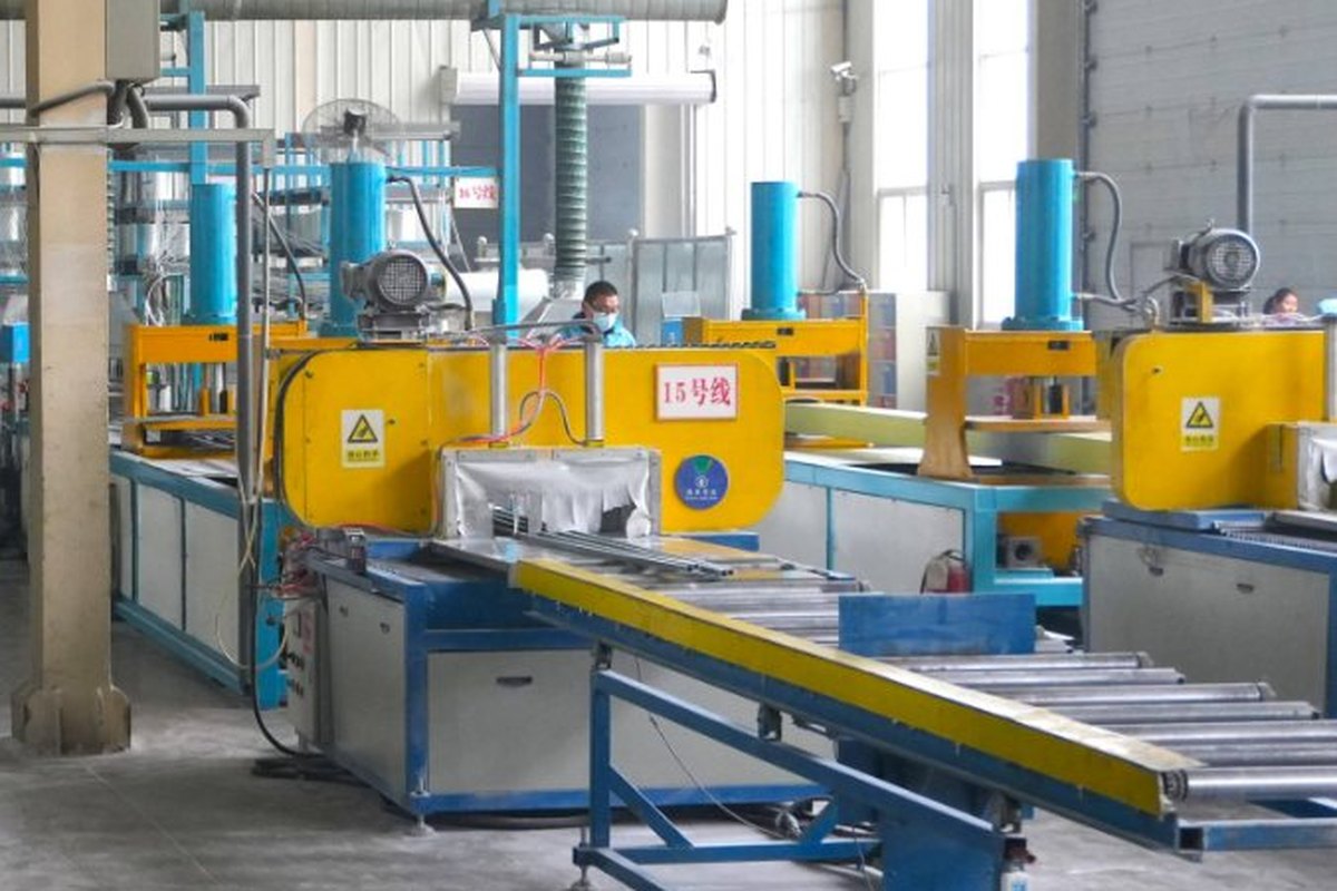
A pultrusion line is unusually honest. Every metre of profile carries a record of the last thirty seconds of process history on its surface, and the defect that appears at the die exit is usually the visible end of a problem that started in the resin bath, the roving creel or a heater band three metres upstream. The difficulty is not detecting defects; it is not misdiagnosing them. "Raise the temperature" and "slow the line down" are the two most common responses, and between them they fix perhaps half the cases and make the other half worse.
This guide is organised as a diagnostic sequence rather than a catalogue. It covers the five defect families that account for most rejections, the process window that produces them, the measurements that separate one cause from another, and a corrective-action order that changes one variable at a time. Product references point to the equipment and profiles involved: the FRP pultrusion production line, pultruded structural profiles and pultruded angle profiles.
1. Read the Defect Before You Touch the Die
Surface defects in pultrusion trace back to five root-cause families. They overlap, but they produce different signatures, and the signature is what tells you where to look first.
| Root-cause family | Typical surface signature | Where it usually starts | First check |
|---|---|---|---|
| Resin formulation | Blistering, tacky surface, discoloration, low Barcol | Bath, initiator dosing, filler lot | Gel time and bath viscosity against the batch record |
| Die thermal profile | Longitudinal cracks, uneven cure, warp, die-line-heavy surface | Heater bands, thermocouple placement | Actual die-wall temperature along the length, not the controller set point |
| Pull speed and tension | Fibre wash, waviness, dimensional drift, dry spots | Puller, creel brakes, preformer | Actual line speed and roving tension per position |
| Tooling condition | Scratches, pull marks, roughness, flash | Die entry radius, chrome, clearance | Die bore inspection and last polish date |
| Impregnation | Dry spots, white fibre, porosity, delamination | Bath, injection block, preformer | Wet-out at the die entry, not at the exit |
Before changing anything, record four things: where the defect sits around the section (top, bottom, left, right), whether it is continuous, periodic or random, when it started relative to the last material or setup change, and whether the pull force moved at the same time. Those four answers eliminate most of the table before a wrench is picked up.
A defect that repeats every 1.2 metres is not a chemistry problem. It is a roll, a guide, a preformer or a puller cycle with a 1.2 metre period. Measure the spacing before you measure the temperature.
2. The Process Window You Are Actually Holding
A pultrusion die is not a uniform hot block. It is a sequence of three thermal duties: bring the resin down in viscosity and finish wet-out, gel it, then cure it before the profile leaves the exit. Published die profiles for unsaturated polyester place the preheat zone at roughly 80–110 °C material temperature, the gel zone at 110–140 °C and the cure zone at 140–180 °C, with the set points on the heaters typically 10–20 K above the material temperatures.
| Zone | Share of die length | Typical set point | What must happen there |
|---|---|---|---|
| Preheat / wet-out | 15–20 % | 115–125 °C | Viscosity falls, air leaves, roving is fully impregnated before gel |
| Gelation | 30–40 % | 140–150 °C | Crosslinking starts; gel should occur within 30–40 % of die length |
| Cure | 40–50 % | 165–175 °C | Conversion completes; Barcol develops; part shrinks away from the die wall |
The most useful single number in that table is the gel-point location. If gelation happens too early, the resin is still viscous when it sets, pull force rises and the surface tears; if it happens too late, the profile exits before the core is cured and blisters appear minutes later on the rack. A practical target is gelation at 30–40 % of the heated length.
Residence time connects the die length to the line speed. In a 900 mm die the residence time falls from 360 seconds at 150 mm/min to 45 seconds at 1,200 mm/min.
| Pull speed | Residence time in a 900 mm die | Thickness that can be heat-soaked | Comment |
|---|---|---|---|
| 150 mm/min | 360 s | Up to about 20 mm | Thick sections and high-Tg epoxy |
| 250 mm/min | 216 s | About 12 mm | Heavy structural shapes |
| 400 mm/min | 135 s | About 10 mm | Typical 8–10 mm bar |
| 600 mm/min | 90 s | About 6–7 mm | Standard structural profile |
| 900 mm/min | 60 s | About 5 mm | Thin tube and flat bar |
| 1,200 mm/min | 45 s | About 3–4 mm | Thin, simple sections only |
Those thickness numbers come from a simple heat-conduction check: for a glass/polyester laminate with a through-thickness diffusivity of about 0.175 mm²/s, the centreline needs roughly 51 seconds to respond when the half-thickness is 3 mm, 143 seconds at 5 mm and 205 seconds at 6 mm. In a 900 mm die those correspond to maximum speeds of about 1,050, 380 and 260 mm/min. The fact that commercial lines run 3 mm profiles at 800–1,200 mm/min while the thermal limit is above 4,000 mm/min tells you what actually limits thin profiles: not heat penetration, but surface cure, pull force and die wear.
3. Blisters and Voids: The Gas Has to Come From Somewhere
A blister is a gas bubble that formed faster than it could escape. There are only four realistic sources in a polyester pultrusion: water, styrene, air, and volatiles from filler or initiator decomposition. They produce different positions and timing.
| Observation | Probable source | Discriminating check |
|---|---|---|
| Blisters appear seconds after the die exit, along the whole length | Moisture in roving or filler | Dry a roving sample at 105 °C and reweigh; check filler lot moisture |
| Blisters in patches, often after a creel change | Wet roving from a part-used package | Compare package storage history and humidity log |
| Blisters only on thick sections, centre of the profile | Exotherm and styrene vapour trapped by a cured skin | Thermocouple in the core; look for an exotherm peak above 200 °C |
| Fine porosity rather than discrete blisters | Air entrained in the bath or at the injection block | Inspect bath return flow and injection pressure |
The moisture arithmetic is worth doing once, because it explains why "a little damp roving" is not a minor issue. At 150 °C, 0.2 % water by mass produces about 3.9 litres of steam per kilogram of compound at atmospheric pressure, or 0.8 litres at a cavity pressure of 5 bar. At 0.5 % water the figures are 9.8 and 2.0 litres. A void that starts as 0.8 litres per kilogram has no route out of a die that is sealed by cured resin on all four sides, so it ends up as a blister under the surface veil.
The corrective order follows from that arithmetic:
- Dry the reinforcement. Store roving below 50 % RH, or pre-dry at 80–100 °C for 2–4 hours before a critical run.
- Verify filler and paste moisture. A part-used filler bag is the most common hidden source.
- Check the initiator dose. An over-catalysed batch gels earlier, traps gas and runs a higher exotherm.
- Add vacuum assist at the die entry if the gas load cannot be reduced further. It removes entrained air, not water vapour generated inside the curing laminate.
Raising the die entry temperature helps only if the problem is resin viscosity at the inlet; raising the cure-zone temperature on a moisture problem simply makes the blister bigger.
4. Dry Spots and Fibre Show-Through
A dry spot is white, hairy and unmistakable: fibre that has not been wet by resin. Fibre show-through is the milder version, a visible glass texture under a thin resin skin. Both are wet-out failures, but they occur at different places in the line.
Bath viscosity is the first variable. Pultrusion-grade polyester is typically supplied at 500–2,000 mPa·s at 25 °C, and most lines run best with a bath in the 1,000–1,500 mPa·s range. Too low and the roving carries too little resin into the die; too high and the resin cannot penetrate between individual filaments before gelation. Bath temperature control matters more than most operators expect, because a 10 K rise can halve the viscosity and change the resin pickup on every roving at once.
Fibre content is the second variable. Structural pultrusions usually run 60–70 % glass by mass, which corresponds to roughly 42–52 % by volume and a laminate density of 1,756–1,903 kg/m³. At 70 % by mass the tow is dense and the resin has very little space to travel between filaments, so wet-out depends on good spreading, adequate tension and a long enough bath path.
| Glass content, % by mass | Fibre volume fraction | Laminate density | Wet-out difficulty |
|---|---|---|---|
| 60 % | 41.5 % | 1,756 kg/m³ | Moderate; forgiving of line speed |
| 65 % | 46.7 % | 1,826 kg/m³ | Standard structural grade |
| 70 % | 52.4 % | 1,903 kg/m³ | High; needs spreading, tension and slower speed |
Where the dry spot sits tells you which of those variables to check first:
- One side only. Suspect the preformer, a rubbing guide or a damaged comb that is stripping resin before the die entry.
- Centre of a bundle. Suspect tension. Loose roving opens and accepts resin; tight roving stays closed and the core remains dry.
- Only at higher line speeds. The bath path is too short for the available residence time. Lengthen the bath, raise the bath temperature within the resin pot-life limit, or reduce speed.
- Random, with white fibre and resin-starved patches on the surface. Suspect resin pickup: bath level, doctor bar setting or roving count per position.
5. Die Lines, Scratches and Pull Marks
These three are often reported as one defect and are three different problems. A die line is a continuous longitudinal ridge or groove that replicates a feature on the die surface. A scratch is a discrete mark with a start and an end, usually caused by a hard particle passing through. A pull mark is a smear or matt band caused by friction and local tearing as the part shrinks against the die.
| Feature | Appearance | Cause | Action |
|---|---|---|---|
| Die line | Continuous, same position, mirror-smooth | Polishing direction, chrome damage, die lip nick | Repolish along the pull direction; inspect chrome; do not polish across the bore |
| Scratch | Starts and stops; may repeat at a roll circumference | Grit, cured resin chip, damaged guide | Find the particle; clean the bath and preformer; replace guide |
| Pull mark | Matt band, sometimes with fine tearing | Excess friction, insufficient release, early gel | Check release agent, die entry temperature, shrink gap |
| Orange-peel texture | Uniform roughness over the whole surface | Die bore too rough, or resin-rich surface curing too fast | Measure die Ra; adjust cure-zone temperature |
Surface finish is a specification, so it should be measured. A die bore polished to Ra 0.4 µm will replicate a mark 5 µm deep as a feature 12.5 times the surface roughness, and a 25 µm mark as 62.5 times. That is why a "small" nick in the chrome is visible on every metre of profile and why polishing with the wrong abrasive makes the problem worse rather than better.
Cleaning matters as much as polishing. Cured resin stuck at the die entry changes the effective taper, increases pull force and creates a matt band. Brass or wood scrapers and a proper release solvent are appropriate; abrasive paper across the bore is not.
6. Longitudinal Cracking and Thermal Stress
Cracks that run parallel to the pull direction are a thermal-stress signature. The surface cures before the core, the core then cures and shrinks against a rigid skin, and the resulting tensile stress is released as a crack when the profile cools or is cut.
- Zone 2 too hot. A gel zone 20–30 K above the rest of the profile cures the skin early. Reducing the zone by 5–10 °C is the first move.
- Steep gradient between zones. A step of more than about 20 K between adjacent zones produces a thermal shock at the transition. Ramp the set points instead of stepping them.
- Line speed too high. The residence time is too short for the core to reach conversion, so the part exits with a partly cured centre and cracks on cooling. A 10–15 % speed reduction is a diagnostic test, not a cure.
- Brittle resin or over-catalysed batch. High-styrene vinyl ester at low temperature, or an initiator overdose, both reduce elongation and make cracking more likely.
Thermal contraction explains why cracks appear after the saw rather than at the die. Over a 6 m length, an axial CTE of 8 µm/m·K and a 130 K cooling range gives 6.2 mm of contraction; a transverse CTE of 25–30 µm/m·K gives 19.5–23.4 mm. The axial and transverse movements differ by a factor of three, and if the laminate is not balanced the difference becomes camber or a crack at a constrained edge.
7. Dimensional Drift, Twist and Camber
Dimensional complaints usually arrive as "the profile is out of tolerance" without saying which tolerance. Pultruded shapes have several independent ones, and they are not interchangeable.
ASTM D3917-23 is the reference for standard pultruded shapes. Its cross-section table allows ±4 % on die-struck dimensions, capped at ±0.094 in (2.39 mm), and ±10 % on wall thickness with a floor of ±0.010 in (0.25 mm). It separates straightness, camber, twist, flatness and angularity, and it deliberately treats them as different measurements. Length tolerance is unilateral and widens in steps with length, so the exact step for the ordered length has to be read from the table rather than extrapolated as a percentage.
| Characteristic | ASTM D3917-23 allowance | How it is usually misapplied |
|---|---|---|
| Die-struck dimension | ±4 %, maximum ±2.39 mm | Treated as a percentage of the finished part rather than the die dimension |
| Wall thickness | ±10 %, minimum ±0.25 mm | Measured at one point instead of the mean of several |
| Straightness | Measured with the part resting on a flat surface, weight minimising deviation | Measured on a bench with the part unsupported, which adds gravity deflection |
| Camber | A separate tolerance from straightness | Reported as straightness, so the real deviation is never assessed |
| Twist | A separate tolerance for bars and shapes | Ignored until assembly, when bolt holes will not line up |
EN 13706-3:2002 is often quoted alongside ASTM D3917, but it does a different job: it defines the E23 and E17 grades through effective flexural modulus and the associated mechanical properties, not through dimensional tolerances. Quoting "E23" as if it were a tolerance class is a common specification error.
Camber and twist are usually laminate-balance problems rather than die problems. A profile with all the reinforcement in the pull direction shrinks more across the width than along the length, and it will bow towards the stiffer face. Adding transverse plies, balancing the surface veils, or symmetrically stacking the mat on both faces reduces the differential. If the camber changes with line speed but not with temperature, suspect differential cooling on the two sides of the die rather than the laminate.
8. Pull Force Is a Trend, Not a Diagnosis
Every pultrusion line has a pull force, and almost none of them log it. That is a missed opportunity, because pull force is the earliest indicator of several failures: resin build-up at the die entry, gradual cure migration upstream, reinforcement compaction, guide friction and contamination.
| Pull-force pattern | What it suggests | What to inspect |
|---|---|---|
| Slow, steady rise over hours | Resin build-up or cure moving upstream | Die entry taper, heater drift, bath temperature |
| Sudden spike, then recovery | Roving tangle, knot or guide jam | Creel, guides, preformer |
| Oscillation with a fixed period | Puller hydraulic or control cycling; intermittent build-up | Puller pressure, encoder, grip condition |
| High from start-up | Die too cold at entry, excessive compaction, poor release | Entry temperature, preformer clearance, release agent |
The absolute value of pull force is not transferable between lines, dies and profiles. What is transferable is the baseline for one setup: record the force at the accepted process point, then treat a 15–20 % deviation as a signal to investigate before adjusting anything.
9. A Measurement Routine That Separates Causes
Most defect investigations fail because too many things are measured after the change rather than before it. The following set is small enough to run every shift and specific enough to discriminate between the five root-cause families.
| Measurement | Instrument or method | Frequency | What it rules out |
|---|---|---|---|
| Bath viscosity and temperature | Brookfield or cup viscometer at bath temperature | Start of shift and after any resin addition | Wet-out and resin pickup problems |
| Gel time | Standard cup gel test at the die temperature | Every resin batch | Initiator or promoter error |
| Die-wall temperature, five points | Contact probe or embedded thermocouples | Weekly and after any heater work | Zone drift and heater failure |
| Pull force | Line logger, trended | Continuous | Build-up, friction, upstream cure |
| Barcol hardness | ASTM D2583 | Every shift, five readings | Under-cure; use 90 % of the same-resin baseline as the floor |
| Density | ISO 1183 | Every batch | Void content and glass content drift |
| Glass content | ISO 1172 burn-off | Every batch or per coil | Roving count or resin pickup error |
| Water absorption | ISO 62 | Type test and after formulation change | Porosity and incomplete cure |
| Dimensions and straightness | ASTM D3917-23 methods | First article and every coil | Die wear, puller slip, laminate imbalance |
| Visual defects | ASTM D4385 classification | 100 % online, plus sample audit | Provides the vocabulary for accept/reject decisions |
Two of those deserve emphasis. Barcol hardness is only meaningful against a baseline from the same resin system: a reading of 38 is acceptable for one compound and unacceptable for another, so the acceptance floor should be written as "not less than 90 % of the qualification baseline", which for a baseline of 45 is 40.5. And visual acceptance needs a written severity scale, because "some die lines" is not a disposition; ASTM D4385 exists to turn that phrase into a category and a limit.
10. Corrective Action: Change One Variable at a Time
The order of correction matters because several fixes interact. Slowing the line and raising the temperature both increase cure, but they change the thermal gradient in opposite directions, so doing both at once destroys the evidence. A defensible sequence is:
- Verify the material. Resin batch, gel time, bath viscosity, filler moisture, roving package condition. This costs nothing and eliminates the largest single group of causes.
- Verify the tool. Die entry cleanliness, chrome, bore finish, guide wear, preformer alignment. A five-minute inspection explains most scratches and pull marks.
- Verify the thermal profile. Measure the die wall at five points, not the controller display. Correct any zone more than 5 K from its set point before changing the set point.
- Change one thermal variable by 5–10 K. Hold for at least five die lengths, then sample. Record pull force and Barcol at the same time.
- Change line speed by 10–15 %. Again hold for five die lengths. If the defect frequency changes with speed, the cause is residence-time related; if it does not, it is material or tooling.
- Only then change the formulation. Initiator level, release agent, low-profile additive or resin toughness. Formulation changes take the longest to validate because they alter gel time, pull force and surface finish together.
A trial record should carry the baseline values, the single change, the time of the change, the length of profile produced before sampling, and the measured result. Without that record, a successful fix becomes folklore and cannot be repeated when the defect returns with the next batch.
Finally, keep the process window and the product specification separate. The window is what the line can hold; the specification is what the customer needs. A profile that meets ASTM D3917 tolerances but has a die line through a sealing surface is still a reject, and a profile with a cosmetic mark outside the agreed severity scale is still acceptable. Writing both down is what turns a defect argument into a quality decision.
For the upstream and downstream topics, see the pultrusion machine guide for heating zones and die design, custom pultruded profiles for tooling and tolerances, pultruded compression members for what section imperfections do to buckling, FRP machining for what happens after the saw, and UV weathering and gelcoat for surface appearance over time. The equipment and profiles are here: FRP pultrusion production line, FRP profile pultrusion line, pultruded structural profiles and pultruded building profiles.
Need help selecting FRP products?
Our engineers answer technical questions free of charge.
Ask an Engineer on WhatsApp