
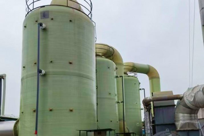
An FRP tank that survives corrosion for twenty years can still be written off in ninety seconds of ground motion. The failure mode is rarely the laminate: it is the connection between a light, elastic shell and a heavy foundation. A filament-wound tank weighs a fraction of the steel tank it replaces, and the weight it inherits when you fill it with 170 m³ of liquid is not mobilised to hold it down, because only the shell, roof and permanently attached steelwork count as stabilising dead load. That single fact drives the whole seismic restraint design.
This guide sets out how the seismic demand on an FRP tank or vessel is actually calculated, how it reaches the concrete, and where filament-wound construction changes the answer compared with a steel or concrete tank. The worked example below uses a filament-wound vertical tank of the type used for chemical and acid service, such as our FRP vertical storage tank for chemical industry, but the same procedure applies to any on-grade vessel. All force and moment values come from a calculation script so the arithmetic can be checked line by line.
1. Why Seismic Design of an FRP Tank Is Not a Steel Tank Problem
Seismic demand on a liquid-filled tank is not a single force. It is a two-mass dynamic problem, and the two masses behave so differently that they must be treated separately before any bolt is sized. Housner's 1963 impulsive-convective decomposition, later extended by Veletsos and Yang (1976) and Haroun and Housner (1981), remains the basis of every modern tank seismic code, including ASCE 7-22 and Eurocode 8.
What changes when the tank is FRP:
- No yield plateau. A filament-wound laminate is essentially linear-elastic to failure. There is no plastic hinge to redistribute a local overload, so an anchorage detail that relies on yielding to shed load will instead crack or delaminate.
- Low axial modulus. Axial modulus of a typical biaxial FRP shell is of the order of 10-15 GPa, roughly one-tenth of steel. The same membrane force produces ten times the strain, so connection stiffness - not strength - often controls the detailing.
- Almost no stabilising dead weight. A DN6000 x 6000 mm FRP tank with a 20 mm shell carries perhaps 40 kN of shell, roof and permanent steelwork. The liquid does not count for uplift resistance in most code formulations. A steel tank of the same duty would contribute several hundred kN.
- Anisotropy. Hoop and axial properties differ by a factor of two or more, so the shell's ability to resist the vertical compression band that seismic overturning creates on the windward side must be checked in the axial direction only.
The engineering consequence is unavoidable: FRP tanks default to anchored construction in any area where seismic design is required, and the anchorage - not the shell - is usually the governing element in the design review.
2. Which Code Governs, and What Each One Actually Gives You
There is no single FRP tank seismic standard. In practice four documents are used together, and knowing which one answers which question prevents the most common submittal error - designing the shell from one code and the anchorage from another.
| Document | What it provides | What it does not cover |
|---|---|---|
| ASCE/SEI 7-22, Section 15.7 | Seismic design of tanks and vessels supported on grade: impulsive / convective decomposition, base shear, freeboard rules | Material-specific detailing; no tabulated response modification factor row for FRP laminates |
| EN 1998-4:2025 (Eurocode 8, Part 4) | Seismic design of silos, tanks, pipelines, towers and chimneys. Published 1 October 2025, replacing EN 1998-4:2006 and EN 1998-6:2005. Force-based approach as the standard procedure; SD, DL and OP limit states | Explicit FRP design rules, but the second-generation drafting explicitly states the analysis principles may also be applied to tanks of other materials such as GFRP |
| API 650 Annex E | Practical period, sloshing height and self-anchoring screening formulas widely borrowed by FRP tank suppliers | Written for welded steel tanks with an attached annular bottom plate that can yield; the self-anchoring logic is not transferable to FRP |
| ANSI/AWWA D103 (Sections 5.9 and 14) | The clearest published method for converting an overturning moment into anchor bolt tension, and for the anchor chair load case | Written for bolted carbon steel water tanks; the load model is transferable, the detailing is not |
On ductility credit, be conservative and explicit. Eurocode 8 for tanks on ground uses the elastic spectrum, effectively a behaviour factor of 1.0 - no ductility credit at all. If your basis of design assigns an R (or q) greater than 1.0 to an FRP tank, that credit must be justified by a demonstrated, tested energy-dissipating detail, and it should be recorded in the design report rather than assumed by default.
3. The Two-Mass Model, Assembled Step by Step
The procedure in ASCE 7-22 is short once the vocabulary is clear. The liquid inside the tank is split into an impulsive portion that moves in unison with the shell, and a convective portion that sloshes at its own low frequency. The base shear is the sum of two terms:
| Quantity | Formula / source | Worked value (DN6000 tank) |
|---|---|---|
| Convective period Tc | Tc = 1.04 sqrt(D tanh(3.68 H/D)) with D and H in metres (API 650 Annex E form) | 2.55 s |
| Impulsive period Ti | From the structural model of shell plus impulsive content | 0.25 s (assumed for this example - confirm by analysis) |
| Impulsive spectral acceleration Sai | Design spectrum at Ti | 1.00 g (constant-acceleration plateau) |
| Convective spectral acceleration Sac | Design spectrum at Tc; note the code assigns 0.5 % damping to the sloshing mode | 0.236 g (= SD1 / Tc) |
| Impulsive base shear | Vi = Sai Wi / (R / Ie) | 958.6 kN |
| Convective base shear | Vc = Sac Ie Wc / 1.5 | 87.9 kN |
| Total base shear | V = Vi + Vc | 1,046.5 kN |
| Overturning moment | M = Vi hi + Vc hc | 2,749 kN.m |
Inputs for the example: inside diameter 6.0 m, design liquid height 6.0 m, liquid specific gravity 1.2 (169.6 m³, 1,997 kN), tank and permanent steelwork 40 kN, SDS = 1.00 g, SD1 = 0.60 g, R = 1.5, Ie = 1.0, effective mass split Wi / Wc = 0.72 / 0.28, and lever arms hi = 0.40 H and hc = 0.85 H.
Two things in that table deserve attention. First, the convective term is only 8.4 % of the base shear - but it acts at 5.1 m instead of 2.4 m, so it contributes a disproportionate share of the overturning moment and almost all of the freeboard demand. Second, the assumed mass split and lever arms must be replaced with the coefficients for the actual D/H ratio from the code tables; they are stated here so that the downstream anchorage arithmetic can be followed, not because 0.72/0.28 is universal.
4. Freeboard: The Trap That Quietly Increases the Base Shear
Freeboard is usually treated as an overflow problem. It is also a force problem, and this is where low-cost FRP tank construction is at its most vulnerable, because a flat or shallow-domed roof with 100-150 mm of head space is normal practice.
ASCE 7-22 requires the design sloshing wave height to be computed, and the freeboard requirements then depend on the risk category: full wave height for the highest consequence category, a reduced proportion at lower categories, and freeboard is always required for the highest risk category. When the freeboard actually provided is less than the computed sloshing height, the sloshing liquid impinges on the roof, and the code commentary gives a way to approximate the resulting roof pressure. But the more damaging consequence is stated plainly in the standard: the restricted convective mass converts into an impulsive mass, and that conversion must be accounted for in the tank design.
The arithmetic on the worked example shows why this matters. If the full sloshing mass converts to impulsive, the impulsive base shear rises from 958.6 kN to 1,331.4 kN, an increase of 38.9 %, and the total base shear rises by 27.2 %. An anchorage sized on the basis of "we provided a little freeboard" can be under-strength by more than a quarter without any of the input data being wrong.
A tank with a fixed roof and 150 mm of head space in a seismic region is not a cheaper tank. It is a tank whose impulsive mass has quietly grown, and whose anchorage has to be designed for a base shear that the supplier's catalogue calculation never mentioned.
5. Turning the Moment into Bolt Tension
AWWA D103 gives the clearest published route from overturning moment to bolt force, and the form is directly usable for an FRP tank once the stabilising dead weight is entered honestly:
Ps = 4 Ms / (N d) - W / N
where Ms is the seismic overturning moment, N the number of anchor bolts, d the diameter of the anchor bolt circle, and W the weight of shell, roof and permanent accessories available to resist uplift. Note what is absent: the liquid. On the worked example, W is only 40 kN against a 1,997 kN liquid load, so the second term contributes a negligible 3.3 kN per bolt of relief.
| Bolts N | Bolt circle d (m) | Ps per bolt (kN) | x 2.5 overstrength (kN) |
|---|---|---|---|
| 12 | 6.40 | 139.8 | 349.6 |
| 16 | 6.50 | 103.2 | 258.0 |
| 20 | 6.60 | 81.3 | 203.2 |
| 24 | 6.70 | 66.7 | 166.8 |
An M24 grade 8.8 bolt (tensile stress area 353 mm², ultimate 800 MPa, resistance factor 0.75) has a tension capacity of about 212 kN. At 12 bolts the elastic demand of 139.8 kN is satisfied with a demand-to-capacity ratio of 0.66 - and that is the number most quick checks stop at. It is not the governing number.
ACI 318-19 Chapter 17 applies to anchors in Seismic Design Category C and above. Tension design for seismic actions may be waived only when the seismic tension component is no more than 20 % of the total factored anchor tension in the same load combination - and with a 40 kN tank weight and a 1,046 kN base shear, that exemption will essentially never apply to an FRP tank. The design must then follow one of the four accepted routes, the most common of which amplifies the seismic force by the overstrength factor, typically 2.0 to 3.0. A 0.75 factor is also applied to concrete-controlled tension capacities.
Applying 2.5 to the 12-bolt case gives 349.6 kN per bolt, which exceeds an M24's 212 kN steel capacity outright. The required tensile area becomes 583 mm², beyond M30 (561 mm²). The practical fixes are cheaper than oversized bolts: increase the bolt count. Moving to 20 bolts on a 6.6 m circle reduces the amplified demand to 203.2 kN, back inside M24 capacity. Bolt count and circle diameter are the tuning knobs; bolt diameter alone is the expensive one.
6. Base Rings and Lugs: How the Load Enters the Laminate
Everything above is arithmetic on the foundation side of the interface. The interface itself is where FRP tanks fail, and it fails in three recognisable ways.
| Detail | Check | Worked value | Verdict |
|---|---|---|---|
| Bolt through the shell wall (t = 12 mm) | Bearing stress = T / (d t) | 485 MPa | Rejected: roughly four times a typical 120 MPa laminate bearing allowable |
| Bolt through the shell wall (t = 20 mm) | Bearing stress | 291 MPa | Rejected: DCR 2.4 |
| Bolt through the shell wall (t = 25 mm) | Bearing stress | 233 MPa | Rejected: DCR 1.9 - thicker wall does not cure a bearing problem |
| Bonded and wrapped FRP lug, 300 x 300 mm on both faces | Bond shear = T / A | 0.78 MPa on 0.18 m² | Accepted: DCR 0.39 against a 2 MPa design allowable |
| Continuous base ring laminated to the shell | Circumferential load spread | Not quantified here | Preferred for larger tanks; converts point loads into a distributed band |
The conclusion is not subtle. A hold-down bolt cannot simply pass through an FRP shell: even a 25 mm laminate is stressed to nearly twice its bearing allowable by a single M24 at the demand calculated above. The load must be introduced through a laminated-in strap or a continuous ring, sized so that the average bond shear stress across a generous footprint stays in the low single-digit megapascals. Surface preparation, taper and overlap length then control the outcome, which is why the bond detail belongs on the tank drawing and not on the civil works package.
Check the shell side as well. On the worked example, the overturning moment produces a peak axial membrane stress of 4.86 MPa, about 19 % of a 25 MPa long-term axial allowable, and a membrane strain of roughly 0.05 % - comfortably inside the 0.10-0.20 % corrosion-barrier strain limits used in the RTP-1 framework. The shell is not the problem. The point at which the load enters the shell is.
7. Sliding, Shear and Sway Bracing
Uplift gets the attention, but a light tank with a slippery base slides long before it tips. The friction check borrows the API 650 sliding form, Vs = mu (1 - 0.4 Av) W, with mu typically taken as 0.4 for a tank bottom on a sand cushion and W the total gravity load, including the liquid.
| Friction coefficient | Sliding resistance (kN) | Demand (kN) | Result |
|---|---|---|---|
| 0.30 (elastomeric pad on smooth concrete) | 562 | 1,046 | Fails: mechanical shear restraint required |
| 0.40 (bottom on sand cushion) | 750 | 1,046 | Fails: demand is 1.40 times resistance |
| 0.50 (roughened base ring on concrete) | 937 | 1,046 | Still marginal |
Three consequences follow. First, shear must be carried by a mechanical device - shear lugs, a keyed base ring or dowels - not by friction alone. Second, if an elastomeric pad is placed under the tank to level the base and reduce local stress, the friction coefficient drops and the shear restraint requirement rises; the two decisions cannot be made independently. Third, shear lugs must be designed on the FRP side with the same care as the tension lugs, because a shear lug loaded against a laminate edge produces bearing and prying, not clean shear.
For tall or slender vessels, add a lateral restraint higher up. A sway brace or tied-back lug at two-thirds height reduces the base moment considerably and is far easier to detail than a heavier base ring, but it introduces a new load path into the shell that needs its own local reinforcement and its own allowance for thermal movement between the vessel and the structure it is braced to.
8. Horizontal Vessels on Saddles
Horizontal FRP tanks are supported on saddles, and the restraint logic is different in three ways. The details below apply to filament-wound horizontal vessels such as our horizontal FRP storage tank, where saddle position is set at the factory and cannot easily be changed on site.
- Uplift is resisted through the saddle, not the shell. Hold-down straps over the shell must bear on a saddle liner or elastomeric pad, never directly on the laminate; a steel strap in direct contact with FRP will fret through the corrosion barrier under vibration.
- Longitudinal restraint is the neglected load case. Seismic base shear along the vessel axis produces a sliding force on the saddles and a couple that tends to rock the vessel about the saddle line. One saddle should be fixed and the other allowed to slide, with the fixed saddle taking the longitudinal load.
- Saddle spacing controls the shell stress. Saddle position, not bolt size, is usually the governing variable for a horizontal FRP vessel, because the shell spans between saddles under the operating weight plus the vertical seismic component.
9. Combining Seismic With Everything Else
Seismic load never acts alone on an FRP tank. The load combinations that govern are usually not the ones that look largest in isolation:
- Seismic plus thermal. A tank in a hot chemical service expands; a rigid anchor that blocks that expansion converts it into a shell stress or a support reaction. Plan the sliding direction before you place the fixed lugs.
- Seismic on an empty tank plus wind. The stabilising weight is gone, the projected area is unchanged. This frequently governs the anchorage of small tanks in high-wind regions.
- Seismic plus nozzle loads. Rigidly connected piping delivers both its own seismic inertia and the tank's wall movement to the same shell penetration. A flexible connection at the first nozzle is often cheaper than reinforcing every penetration.
- Seismic with a partially filled tank. The mass split changes with the fill level, and intermediate levels can produce convective behaviour that the full-tank analysis never sees.
10. Inspection, Testing and What to Record
Anchorage is only as good as its installation and its paper trail. The items that decide whether the design intent survives contact with the site:
| Stage | Record to capture |
|---|---|
| Design | Site SDS / SD1 values and source, risk category, R (or q) with justification, mass split and lever arms used, freeboard provided versus computed |
| Fabrication | Lug lamination schedule, overlap and taper dimensions, secondary-bond surface preparation record, Barcol readings against the laminate reference |
| Installation | Bolt circle diameter as built, embedment depth measured, anchor torque and whether washers or isolating pads were fitted, foundation level survey |
| Commissioning | Hydrostatic test record with the restraint in place, nozzle alignment at operating temperature, confirmation that all shipping restraints were removed |
| In service | Annual visual check of lugs, anchor corrosion and pad condition; torque verification of anchor bolts; re-check after any seismic event above the design threshold |
Two details decide whether the anchor survives chemically as well as structurally. Use stainless or hot-dip galvanised anchors, and separate the anchor from the FRP and from a steel base ring with an isolating washer or pad to avoid a galvanic couple. Then bond the tank separately for static dissipation - the isolation required for corrosion control and the bonding required for static are both real requirements, and they must be satisfied by different components rather than by compromising either.
11. Specifying Restraint With the Tank, Not After It
The restraint design needs four pieces of information that only the tank supplier can provide: the operating and empty weights, the centre of gravity, the shell laminate schedule with axial properties, and the anchorage detail drawing with the lug bond dimensions. Buying the tank first and designing the anchorage afterwards is how light FRP tanks end up on foundations designed for steel tanks, with a factor that looks acceptable on paper and is not there in an earthquake.
Ask for the anchorage detail as part of the tank quotation, and ask for it in writing: lug count and position, laminate build at each lug, the torque limit for the flange and anchor bolts, and the maximum permitted foundation level tolerance. Those numbers take an hour to produce at the factory and weeks to fix on site.
Related reading on this site: FRP storage tank transport and installation covers cradles, foundations and hydrotesting; FRP vessels to ASME Section X and RTP-1 explains the class and certification rules that sit behind the strain limits quoted above; tank nozzle and manway design covers penetration reinforcement and bolt torque; and bolted connections in pultruded FRP sets out the bearing, edge-distance and spacing rules that also govern anchor lugs. For tanks that must be restrained in ground, see support spacing and guided fixings, and for stacks and towers subject to dynamic loads, see free-standing FRP stacks.
Need help selecting FRP products?
Our engineers answer technical questions free of charge.
Ask an Engineer on WhatsApp