
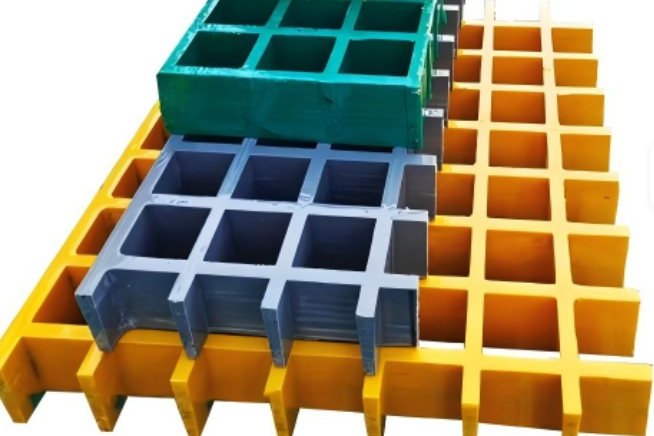
A data hall and a battery room usually sit a few metres apart on the same site, share a fire alarm loop and are specified by the same consultant — yet a walkway deck that is impeccable in one room is an active liability in the other. The white space is governed by particulate counts, static control and air distribution; the battery room is governed by hydrogen evolution, sulphuric acid mist and a wet, conductive, chemically aggressive atmosphere that destroys galvanised steel from the inside of the section outwards. Glass-reinforced plastic grating and pultruded profiles answer both, but only if the requisition carries the right numbers into each room. This guide sets out those numbers, the standards they come from, and the wording that keeps them from being value-engineered away.
Two warnings before the detail. First, FRP is not one material: a grating panel moulded from orthophthalic polyester and a profile pultruded from vinyl ester differ in tracking resistance, temperature ceiling and fire signature by a wide margin, so a certificate is worth more than a family name. Second, the electrical and the static-control requirements pull in opposite directions in a battery room — one wants an insulator, the other wants a defined leakage path — and the resolution is a deliberate equipotential design, not a product choice.
1. One Site, Two Very Different Rooms
The two rooms share a floor slab and almost nothing else. Writing the requirement matrix before writing the product list is what prevents a generic "FRP grating, fire retardant" line item from being substituted later.
| Requirement | Data hall / white space | Battery room | Reference that drives it |
|---|---|---|---|
| Atmosphere | 18–27 °C at the IT intake, humidity controlled, no chemical load | Hydrogen-bearing, acid mist, occasional electrolyte spill, condensation in winter | ASHRAE TC 9.9; IEEE 484 |
| Walking surface | Demountable, low shedding, static-dissipative, no zinc whiskers | Chemically inert, inert to acid, liftable for cell maintenance | ISO 14644-1; IEC 61340-5-1; NEC Article 480 |
| Void below | Pressurised cold-air plenum at roughly 20–25 Pa, cleaned like a duct | Cable trench, drainage route, spill containment | ASHRAE TC 9.9 |
| Structural duty | Rack feet, crane-lifted CRAC units, pallet trucks in corridors | Racks and monorails, spill trays, occasional cell trolleys | EN 12825; TIA-942-B |
| Corrosion mechanism | None to mild; condensation pitting on coated steel at cut edges | Sulphuric acid mist plus water: acid attack on zinc and on the cut ends of galvanised sections | — |
| Fire question | Smoke and corrosivity inside an occupied, high-value space | Source of ignition must not exist; smoke output of the deck matters little | NFPA 76; NFPA 855; ASTM E84 |
The consequence is a specification split. In the white space the deck is chosen on cleanliness, static behaviour and stiffness under point loads. In the battery room it is chosen on chemical inertness, non-conductivity and cleanability, and the static question is resolved at the earthing bar rather than in the panel.
2. Where Metal Fails — and Why It Fails Quietly
Hotel-load battery rooms are the classic case. Sulphuric acid mist settles on every horizontal surface; where it meets condensation, the pH at the surface of a galvanised section falls into the 2–4 band, and zinc is consumed at a rate measured in tens of microns per year. The failure is not dramatic — it starts at cut edges, bolt holes and the inside of hollow sections, all of which are inaccessible, and it is discovered when a support leg folds or when a white corrosion bloom appears on the floor beneath a rack. Painted steel behaves worse, because the coating shields the corrosion from view while the steel beneath it pits.
The three failure modes that repeat in these rooms are worth naming, because each one has a design answer:
- Cut-edge corrosion. Galvanised sections are protected by a coating that is discontinuous at every shear cut. Coatings repair badly in a humid room; an inert laminate does not need repair.
- Conductive debris. Rust flakes, zinc whiskers and swarf from metal decking are all conductive particles inside a space full of exposed busbars and terminal blocks. In a data hall they are also the contamination that blocks rack filters and bridges board-level traces.
- The inspection blind spot. Nobody lifts a walkway panel to look at the underside of a support that cannot corrode. With FRP the inspection interval can be set by the maintenance regime rather than by the corrosion allowance.
Stainless steel is the obvious metal answer and it works, at a cost multiplier that rarely survives a value-engineering pass, and with a thermal conductivity that makes bare 316 benches uncomfortable to touch next to a warm inverter. FRP occupies the space below stainless on cost and above it on thermal and electrical properties.
3. The Four Electrical Numbers That Decide the Specification
"Non-conductive" is not a specification. Four measured properties carry the electrical design, and a supplier who cannot produce test reports for all four has not been asked the right question.
| Property | Test method | Pultruded / moulded GRP (typical) | What it decides |
|---|---|---|---|
| Volume resistivity | ASTM D257 / IEC 62631-3-1 | 1 × 10¹³ Ω·cm for a 55 wt % glass pultruded polyester; structural grades quoted above 1 × 10¹² Ω·cm | Whether the member can be treated as an insulator at all: GRP is roughly 18 orders of magnitude less conductive than steel |
| Dielectric strength | ASTM D149 / IEC 60243 | About 8 kV/mm (200 V/mil) on a commercial structural pultrusion; higher figures come from thin, dry coupons | Through-thickness breakdown where a live conductor bears on the material |
| Arc resistance | ASTM D495 | About 80 s on the same grade | Whether an arc at a loose terminal carbonises a path across the surface |
| Comparative tracking index | IEC 60112 | A well-formulated glass-reinforced polyester reaches material group I (CTI ≥ 600 V) | Creepage distance — see the next section |
| Relative permittivity | ASTM D150 | Around 4.4 at 60 Hz | Capacitive coupling and induced currents on cable routes |
Volume resistivity and dielectric strength are measured on a specimen, not on a structure. Water absorption, in-service temperature and the condition of a cut edge all reduce the numbers, which is why the certificate should state the conditioning and the specimen thickness. A datasheet value of 20 kV/mm measured on a dry 3 mm coupon tells you nothing about a 38 mm pultruded beam bolted to a wet concrete wall.
The comparison that matters commercially is not GRP against PVC. Rigid PVC has a comparable volume resistivity, so it looks attractive on an insulation datasheet, but its continuous service temperature is far below GRP's and its combustion products are chlorinated. In a room where the fire specification is written around smoke corrosivity, a chlorine-bearing material is the wrong answer regardless of its resistivity.
4. Creepage and Clearance: Where the Deck Becomes Part of the Insulation System
Once a glass-reinforced member separates two live parts — a cable trench cover between busbars, a grating panel between battery terminals, a support block under a busbar — the member stops being furniture and becomes solid insulation. Two distances have to be checked, and they are sized from different inputs. Clearance is the shortest path through air and is set by the impulse withstand voltage selected for the overvoltage category; creepage is the path along the surface and is set by the working voltage, the pollution degree and the material group derived from the CTI.
The pollution degree is the variable most often ignored on industrial sites, and it is the one that moves the answer furthest. IEC 60664-1 defines four degrees from clean and dry (PD1) through normal industrial (PD2) to conductive contamination (PD4). A battery room with acid mist, condensation cycles and periodic washing is not PD1.
| Working voltage (r.m.s.) | PD1, any material group | PD2, group I (CTI ≥ 600) | PD2, group II (CTI 400–599) | PD2, group III (CTI < 400) |
|---|---|---|---|---|
| 400 V | 1.0 mm | 2.0 mm | 2.8 mm | 4.0 mm |
| 800 V | 2.4 mm | 4.0 mm | 5.6 mm | 8.0 mm |
| 1000 V | 3.2 mm | 5.0 mm | 7.1 mm | 10.0 mm |
Minimum creepage distances from IEC 60664-1 Table F.4. Values are indexed on working voltage r.m.s.; for a DC system the DC working voltage is used directly. Reinforced insulation takes twice these values. Linear interpolation is permitted between tabulated points.
Two practical consequences follow. First, a 400 V DC battery string in a PD2 room needs 2.0 mm of creepage on group I material and 4.0 mm on an unclassified polymer — a 100 % penalty for choosing a material with no CTI report. Second, creepage can be bought back without enlarging anything: ribs, grooves, a routed slot and a raised shoulder all lengthen the surface path at almost no material cost, which is how a moulded grating clip or a pultruded busbar support stays compact while meeting the table.
Clearance is a separate check and must not be extrapolated from the creepage figure. IEC 60664-1 tabulates minimum clearance against the required impulse withstand voltage for basic insulation at altitudes up to 2000 m: 0.5 kV → 0.2 mm, 1.5 kV → 0.5 mm, 2.5 kV → 1.5 mm, 4.0 kV → 3.0 mm, 6.0 kV → 5.5 mm. Above 2000 m the clearance values are multiplied by an altitude correction factor — 1.14 at 3000 m, 1.29 at 4000 m, 1.70 at 6000 m — while creepage, being a surface phenomenon, is not corrected in the same way. Sites in highland China or in the Andes therefore change the clearance column only.
5. Battery Room Chemistry: Lead-Acid, VRLA and Lithium Are Not One Problem
The generic phrase "battery room" hides three different atmospheres with three different material lists. Designing one deck for all three is how projects end up with a floor that is simultaneously over-specified for the lithium store and under-specified for the flooded bank.
| Family | What leaves the cell | Gassing behaviour | Consequence for the room |
|---|---|---|---|
| Flooded lead-acid | Hydrogen and oxygen from water electrolysis; sulphuric acid mist carried on the bubbles | Gassing starts near 2.30–2.35 V per cell at 25 °C and rises steeply on equalisation at 2.50–2.65 V per cell; the threshold falls 3–5 mV per °C as temperature rises | Continuous mechanical ventilation with ceiling-level extract, acid-resistant surfaces, spill bunding, no ignition sources |
| VRLA (AGM / gel) | Normally recombines internally; vents on overcharge or thermal runaway | Float at 2.25–2.30 V per cell is largely closed-loop; gassing is a fault condition rather than a duty condition | Ventilation still required, but the design case is the fault; hydrogen detection is good practice |
| Lithium-ion | No hydrogen in normal operation; thermal runaway releases hydrogen fluoride, carbon monoxide and electrolyte vapours | Not a gassing problem in the lead-acid sense at all | Design shifts to NFPA 855 thermal-runaway propagation, deflagration venting and gas detection |
For the deck itself, the flooded room is the one that sets the material. Sulphuric acid mist at pH 2–4 with condensation cycles attacks galvanised steel, aluminium and unprotected carbon steel. Isophthalic polyester holds at the acid concentrations involved provided the temperature stays inside the resin's ceiling; vinyl ester is the safer default where the room also sees alkaline wash-down or where acid concentration can drift. A phenolic system is added when the room is inside a building whose fire strategy requires a low-smoke, low-toxicity lining product. All three are available in the same moulded grating panel format, which is why the resin line on the purchase order, not the word "FRP", is what the room actually receives.
Temperature deserves a line of its own because it is the cheapest reliability lever in the building. The industry rule of thumb, repeated by every major lead-acid manufacturer and embedded in IEEE 484-based sizing practice, is that service life halves for roughly every 8 °C above the 25 °C reference. A room held at 33 °C therefore consumes two battery strings' worth of calendar life to save one air-conditioning stage.
6. Hydrogen: Sizing the Room From a Gassing Rate
Hydrogen is explosive between 4.0 % and 75 % by volume in air and is about one-fourteenth the density of air, so it collects at the ceiling and leaves through the highest available opening. The engineering limit universally applied is 1 % by volume — a 4:1 margin below the lower explosive limit — and the calculation chain that gets you there is short enough to do on one page.
IEEE 484 gives the empirical generation rate for a lead-acid string:
QH2 [ft³/min] = 0.000269 × N × I × C
where N is the number of cells in the string, I is the charging current in amperes (taken at the charger's current limit for the equalisation case, not the float case), and C is the overcharge factor, normally 1.0 to 1.15. The constant 0.000269 ft³ per ampere-minute per cell corresponds to the Faraday production rate of hydrogen divided by two electrons, with a small allowance for overcharge.
The dilution airflow needed to hold the concentration below a chosen ceiling is the generation rate divided by that ceiling expressed as a fraction — that is, Q divided by 0.01 for a 1 % limit. The two worked cases below use the same equations.
| Case | String | Equalise current | H₂ rate at C = 1.0 | Dilution air to hold 1 % | To hold 2 % |
|---|---|---|---|---|---|
| A — small UPS / switchgear room | 60 cells (120 V) | 60 A | 0.97 ft³/min (1.65 m³/h) | 97 ft³/min (165 m³/h) | 48 ft³/min |
| B — large substation bank | 120 cells (240 V) | 150 A | 4.84 ft³/min (8.23 m³/h) | 484 ft³/min (823 m³/h) | 242 ft³/min |
Two further checks normally override the calculation. NEC Article 480.9(A) requires ventilation sufficient to keep hydrogen below the design ceiling, and the NFPA 1 fire code carries a prescriptive minimum of 1.0 ft³/min per square foot of floor area, independent of any gas calculation. A 6 m × 8 m room is 517 ft², so its prescriptive minimum is 517 ft³/min — more than the calculated requirement in both worked cases above. The governing design flow is the greater of the two numbers, with an added margin (1.25 is a common allowance) for duct leakage, filter pressure drop and fan degradation over life.
The number that changes behaviour on site is the failure case rather than the design case. With the extract fan stopped, case B generates 4.84 ft³/min into a 48 m² room at 3 m clear height, which is a volume of roughly 5,090 ft³. A 1 % concentration occupies 50.9 ft³ of that volume, so the room reaches the design ceiling in about ten and a half minutes, and the 4 % lower explosive limit in about forty minutes. That is why the extract fan is interlocked with the charger, why airflow failure has to be alarmed rather than logged, and why the extract grille sits at the highest point of the room instead of at a convenient working height.
7. Fire: Four Standards, Four Different Questions
Fire specifications for these rooms are routinely written as a single sentence and are routinely wrong, because four different documents answer four different questions. Sorting them out before the enquiry goes out saves a test programme later.
| Document | Question it answers | What to demand |
|---|---|---|
| ASTM E84 / UL 723 | How fast does flame spread across the surface, and how smoke-dense is the plume? | Flame spread index ≤ 25 and smoke developed index ≤ 450 for a Class A / Class 1 rating; ask for the actual indices, not the class letter |
| EN 13501-1 | European reaction-to-fire class including smoke and flaming droplets | A class with the smoke and droplet suffixes stated, for example B-s1,d0 — the suffixes are what the fire engineer is checking |
| UL 94 | Does a small vertical specimen self-extinguish? | V-0 for the resin system; note that V-0 is a material screen and is not a substitute for a surface-burning test |
| NFPA 76 / NFPA 855 | What does the room's fire strategy require of everything inside it? | For IT spaces, a low-smoke, low-corrosivity material set; for stationary storage, thermal-runaway propagation and deflagration venting per NFPA 68/69 |
Two points are worth making explicit in the requisition. First, "fire retardant" is not a class: an ASTM E84 flame spread index is a number between 0 and 200, and the Class A band (0–25) and the Class B band (26–75) describe very different materials. Second, NFPA 855 has moved fast — the 2026 edition, effective from the start of 2026, makes large-scale fire testing a core requirement and adds active-ignition provisions for vented flammable gas — so a specification written against an older edition may not match the authority having jurisdiction's current document. Where the battery installation falls under NFPA 855 at all, the material schedule for the room should be re-checked against the current edition rather than inherited from the previous project.
8. Cleanliness: ISO 14644-1 Class 8, Outgassing and the Sub-Floor Plenum
In the white space the deck is part of the contamination control system, not just a walking surface. Enterprise data halls are normally engineered to ISO 14644-1 Class 8, which caps airborne particles at 3,520,000 per cubic metre at 0.5 µm and above, 832,000 per cubic metre at 1 µm and above, and 29,300 per cubic metre at 5 µm and above. Hyperscale operators often hold Class 7 in the primary compute corridors, which is an order of magnitude tighter.
Open-mesh grating helps for a physical reason: the sub-floor void is usually a pressurised supply plenum at roughly 20–25 Pa, and anything that settles on a solid deck's underside is eventually re-entrained, blown to the nearest rack intake and deposited on a heatsink. Open mesh lets the plenum be cleaned and inspected from above without lifting a sealed tile, and it does not trap the concrete dust and cable debris that accumulate in the void.
Two material-level properties matter alongside the geometry:
- Particle shedding. A moulded panel with a sealed, gritted surface sheds far less than an edge-sealed laminate whose cut ends have been left open. Every cut edge should be sealed in the factory or with a supplied resin kit, and the seal should be listed as an inspected item.
- Outgassing. ASTM E595 measures total mass loss and collected volatile condensable material after 24 hours at 125 °C in a vacuum below 7 × 10⁻³ Pa; the screening criteria traditionally applied are TML ≤ 1.00 % and CVCM ≤ 0.10 %. Structural pultrusions generally pass on CVCM, but the value should be requested rather than assumed, because it depends on cure and on post-cure, not on the resin family alone.
Gaseous contamination is a separate axis and is not covered by ISO 14644-1 at all. ANSI/ISA 71.04 classifies the environment by the copper corrosion rate measured on coupons: G1 mild below 300 Å per month, G2 moderate below 1000, G3 harsh below 2000, and G4 severe above 2000. A room near an industrial chlorine or sulphur source can be Class 8 on particles and G3 on gas at the same time, and the deck specification cannot fix that — but knowing the classification prevents the wrong blame being placed on the flooring when corrosion appears on card edges.
9. Load, Span and Static Control: What Goes on the Datasheet
Floor loading in a data centre is normally expressed as a concentrated load at the panel centre, which is exactly the parameter that EN 12825 governs for access floors. The standard derives the rated working load from the measured ultimate load using a safety factor — 2 for the usual case, 3 where a higher factor is specified — and classifies panels by that ultimate load. It also fixes the deflection class at working load and the permanent deformation limit, and it prescribes where the load is applied: a 25 mm square indenter at the centre of the panel, at the edge, and at a point 70 mm diagonally from the top of the pedestal.
| EN 12825 load class | Ultimate load | Working load at safety factor 2 | Typical use |
|---|---|---|---|
| Class 3 | ≥ 8 kN | 4 kN | Light server rooms |
| Class 4 | ≥ 9 kN | 4.5 kN | Standard enterprise data hall |
| Class 5 | ≥ 10 kN | 5 kN | High-density compute |
| Class 6 | ≥ 12 kN | 6 kN | UPS and battery rooms, high-density GPU halls |
Deflection classes run A ≤ 2.5 mm, B ≤ 3.0 mm and C ≤ 4.0 mm measured at working load; permanent deformation is limited to 0.5 mm, and the long-term creep test requires permanent deformation of no more than 0.3 mm after 1000 hours at working load. TIA-942-B ties rack-flooring minimums to the tier level, reaching 6,675 N for Tier III and 8,000 N for Tier IV, and raises the required class by one step in UPS and battery areas — a rule that catches projects that specify the same panel everywhere.
Where grating rather than a solid panel is used for service decks over trenches and plant, the same discipline applies with the panel manufacturer's own load table instead of EN 12825: the span, the bearing-bar depth, the load case (uniform, concentrated, or a cart wheel on a defined contact patch) and the deflection limit all have to be stated, because a grating deflection criterion of span/100 is generous for a catwalk and unacceptable under a rack-moving trolley. The two load tables are not interchangeable, and a supplier who quotes "5 kN" without saying which table it came from has not answered the question.
Static control is the last parameter and the one most often mishandled. IEC 61340-5-1 language for a data hall floor is a surface resistance to ground of 1 × 10⁴ to 1 × 10⁶ Ω for a conductive floor, or 1 × 10⁶ to 1 × 10⁹ Ω for a dissipative floor. Plain GRP sits far above both figures. That is not a defect — it is a design choice with a decision attached:
- If the deck is a walkway in a plant room, high resistance is an advantage and the requirement becomes insulation, not dissipation.
- If the deck is the working floor in an ESD-protected area, the charge path to earth is provided by the earthing system — a designated conductive path through the structure — and the deck must not be counted as that path.
- In a battery room the equipotential bonding of all accessible metalwork, to IEEE 484 and to the local electrical code, is what prevents a person touching two things at different potentials. Non-conductive decking does not remove that requirement; it removes one more incidental conductor from the room.
10. Specification Checklist and the Mistakes That Get Repeated
A requisition that answers the following ten lines is hard to substitute and easy to audit. Everything above collapses into them.
- Resin, stated by family. Isophthalic polyester as the baseline, vinyl ester where the acid load or wash chemistry demands it, phenolic where low smoke and low toxicity drive the fire strategy.
- Electrical data with test references. Volume resistivity to ASTM D257, dielectric strength to ASTM D149, arc resistance to ASTM D495 and a CTI value to IEC 60112, each with the specimen conditioning.
- Creepage and clearance design intent. Pollution degree, working voltage and material group, so the supplier knows the panel is part of the insulation system.
- Fire rating with numbers. ASTM E84 flame spread and smoke developed indices, or an EN 13501-1 class with its s and d suffixes.
- Load case and deflection limit. Named standard, named indenter, named acceptance deflection — not a bare kilonewton figure.
- Cleanliness. ISO 14644-1 class for the space, cut-edge sealing requirements and, where applicable, ASTM E595 results.
- Hardware. A4 stainless fixings throughout, isolating washers under stainless brackets against galvanised steel, and no carbon steel in the battery room.
- Bonding. A defined equipotential scheme and its earthing points, referenced to the electrical code that governs the site.
- Ventilation interface. The deck and the ceiling void are part of the ventilation path in both rooms; the extract arrangement and the interlock belong in the same document.
- Inspection access. Panels must be liftable by one person with a standard tool, and the panel size should be chosen from the maintenance procedure rather than from the cheapest module.
The recurring mistakes are equally predictable. Specifying "FRP grating, fire resistant" and accepting a certificate for a different resin system. Treating an ASTM E84 Class A letter as equivalent to a European B-s1,d0 class. Asking for non-conductive decking and then assuming the room no longer needs equipotential bonding. Using a 400 V creepage figure at 800 V because nobody re-read the table. Installing galvanised clips because they were cheaper, in a room whose whole specification exists because zinc fails there. And sizing ventilation from the prescriptive floor-area minimum in a small room holding an unusually large string, where the gas calculation governs instead. Every one of these is a specification defect, not a product defect — and each is closed by a line of text, which is the cheapest kind of fix available.
Decks and Structures for Rooms Where Failure Is Not an Option
We mould the grating and pultrude the profiles that go into these two rooms, in the resin systems each of them actually needs. Start with the moulded FRP grating range for walkways, trench covers and service decks, and the anti-slip, Class 1 fire-rated grating range where the fire schedule is written around smoke and flame spread. Cable routes through the same rooms are covered by the FRP U-section cable trench and duct range, panel supports and framing come out of the pultruded FRP profile range, and the whole family sits under plates and grates.
For the adjacent decisions, see reading grating load tables for uniform and concentrated loads, step and touch potential with FRP grating in electrical substations, flame spread, smoke and Class 1 panel selection, total cost of ownership against steel grating, FRP electrical insulation components and pultruded cable tray systems for corrosive environments. Send us the room's gas calculation, its pollution degree and its fire schedule, and we will come back with the resin system, the panel schedule and the test reports that match them.
Need help selecting FRP products?
Our engineers answer technical questions free of charge.
Ask an Engineer on WhatsApp