
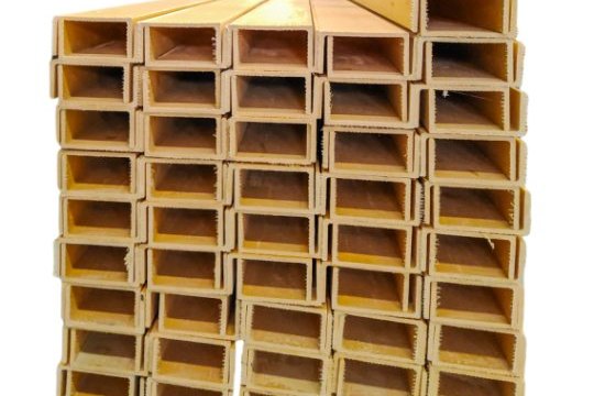
An FRP pedestrian bridge is rarely limited by the strength of its material. Pultruded glass-reinforced polymer is comfortably strong enough for foot traffic at almost any span you would build. What limits it is how far it bends and how it behaves under a walking pace. Deflection and footfall vibration, not stress, decide the girder depth, the beam count and the span, and they are the two things a supplier's strength table does not help you with. This guide covers the live loads that set the design, the deflection limits used across the main codes and why they range from L/300 to L/500, a worked 12 m span in pultruded FRP showing exactly how far a shallow beam falls short and what stiffness is actually required, the vibration criterion that catches designs which pass every deflection check, and the deck, connection and durability decisions that follow.
1. Why the Girder Is Sized by Stiffness, Not Strength
Steel has a modulus of elasticity around 200 GPa. Pultruded FRP has a flexural modulus around 23 to 30 GPa depending on the resin, the reinforcement architecture and the grade of the profile — that is roughly one eighth to one seventh of steel. Allowable stress, on the other hand, is not eight times lower; pultruded FRP design strengths are a substantial fraction of mild steel's yield.
The consequence is geometric. To carry the same load over the same span with the same deflection, an FRP beam needs a much larger second moment of area than a steel beam, because you cannot recover the missing modulus by using more material efficiently — you have to move material further from the neutral axis or use more of it. Depth and section count become the design variables, and both are driven by a serviceability limit rather than a strength limit.
This is not a defect of FRP; it is a different design conversation. It does mean that a conversation which starts with "how strong is the material" will end in the wrong place. The first question is: how much may this bridge deflect, and what does that require?
On a steel footbridge the strength check frequently governs and deflection confirms it. On an FRP footbridge the order is reversed: deflection governs, and the strength check almost never binds.
2. The Standards You Will Actually Be Held To
FRP footbridge design is now reasonably well codified, with one important recent change.
| Document | Status | What it adds |
|---|---|---|
| AASHTO LRFD Guide Specifications for the Design of FRP Pedestrian Bridges, 2nd Edition (2025) | Current, published May 2025, item code GSDFPB-2 | Load and resistance factor design, supplementing the AASHTO LRFD Bridge Design Specifications 10th Edition. Emphasises delegated design, where the manufacturer designs the FRP bridge or deck and its connections to performance requirements set by the owner's designer. |
| AASHTO LRFD Guide Specifications for Design of Pedestrian Bridges, 2nd Edition | Current | The companion document covering pedestrian bridges generally, including the structural systems FRP decks sit on |
| AASHTO LRFD Bridge Design Specifications | 10th Edition, December 2024 | The parent specification; the guide documents are supplements, not replacements |
| EN 1991-2 and national annexes | Current in Europe | Pedestrian loading, dynamic amplification and the vibration serviceability route |
| EN 13706 series | Current | The specification for pultruded profiles, including the E23 and E17 stiffness and strength classes that a manufacturer's data sheet should be declared against |
| National bridge authority guidance | Varies | Where FRP is used in a highway or rail environment, the transport authority's own FRP or buried-structures guidance usually governs deflection limits |
The 2025 second edition of the FRP pedestrian bridge guide is a genuine change in emphasis, not just a refresh. The first edition, published in 2008, was written for FRP truss bridges assembled by bolting pultruded elements together. Since then, pultruded FRP planks and vacuum-infusion moulded FRP panels have become common as bridge decking supported on steel, concrete or timber beams. The second edition covers that composite-material configuration, moves from allowable stress and load factor design to LRFD, and puts the emphasis on delegated design — meaning the manufacturer is responsible for designing and detailing the FRP deck and the connections into a system designed by someone else. If you are buying an FRP deck to sit on a steel girder, that clause is the one that decides which party owns the connection design.
3. Pedestrian Live Load: The Number That Sets Everything
Almost all of the variation between codes comes down to two numbers: the live load and the deflection limit.
| Source | Pedestrian live load | Deflection limit | Applies to |
|---|---|---|---|
| UK transport authority FRP structures guidance | Per highway bridge loading | L/300 | FRP highway bridges and structures |
| US Forest Service FRP trail bridge guide | 4.07 kN/m² | L/400 | FRP trail bridges in recreational settings |
| AASHTO guide specifications, pedestrian bridges | 4.07 kN/m² | L/500 | Pedestrian bridges generally |
| AASHTO guide specifications, FRP pedestrian bridges | 4.07 kN/m² | L/500 | FRP pedestrian bridges specifically |
| JSCE FRP footbridge guidance | 5.0 kN/m² | L/500 main girders, L/400 other components | FRP footbridges |
| EN 1991-2 footbridge loading | 5 kN/m² with a concentrated load case; confirm the national annex | Set by the vibration serviceability route and national practice | European footbridges |
Two observations follow. First, the difference between L/300 and L/500 is not cosmetic: at a fixed stiffness the allowable span changes by roughly the cube root of the ratio, and at a fixed span the required stiffness changes by 67 %. Always establish which limit applies before sizing anything. Second, the live load figures cluster around 4 to 5 kN/m², which is a dense crowd plus dynamic effects; the deflection limit is what actually varies.
4. Why the Deflection Limits Differ So Much
L/300 and L/500 are both defensible, and the reason for the difference is what the bridge is for and how its users will react to movement.
- L/300 is a structural limit. It keeps the structure serviceable and the deck joints working. It is not a comfort criterion — people will feel a bridge deflecting at L/300, and on a flexible FRP deck they may also see it.
- L/400 is where a bridge stops feeling disconcertingly springy to most users. It is the level the US Forest Service guidance adopts for trail bridges, where the setting is informal and users are not in a hurry.
- L/500 is the comfort-centred limit adopted by AASHTO for pedestrian bridges and by JSCE for FRP footbridge main girders. It is also the figure used on the first all-GFRP pedestrian bridge in Taiwan, where the L/500 target translated to a 15 mm allowable deflection on a 12 m class span, with the deck built as GFRP I-girders, an anti-skid sand layer over resin, and connections made with GFRP pins and epoxy adhesive rather than steel.
Where a project mixes frameworks, use the tighter of the applicable limits and say so in the design basis. There is no engineering case for accepting L/300 on a bridge whose users are non-technical members of the public.
5. Worked Example: A 12 m Span in Pultruded FRP
Take a 12 m simply supported footbridge, 1.5 m wide, on four girders. Live load 5 kN/m² plus a 1 kN/m² allowance for deck and beam self weight gives 2.25 kN/m of load and 38 kg/m of permanent mass per girder. Now compare three girders of increasing stiffness.
| Girder stiffness EI | Max span at L/300 | Max span at L/400 | Max span at L/500 |
|---|---|---|---|
| 1.5 × 10⁶ N·m² — a 305 mm deep pultruded I-beam, E = 25 GPa | 5.55 m | 5.04 m | 4.68 m |
| 5.0 × 10⁶ N·m² — a deep box or double-web beam | 8.29 m | 7.53 m | 6.99 m |
| 1.5 × 10⁹ N·m² — a truss or very deep box girder | 11.95 m | 10.86 m | 10.08 m |
That table is the whole story of FRP footbridge design in three rows. A row of ordinary 305 mm pultruded beams is a perfectly good solution up to about four and a half metres at L/500, which covers most boardwalks, platforms and short crossings. Push the span to twelve metres with those beams and the numbers are not marginal — they are absurd:
| Girder stiffness EI | Deflection at 12 m | As a fraction of span | First frequency |
|---|---|---|---|
| 1.5 × 10⁶ N·m² | 405 mm | L/30 | 2.16 Hz |
| 5.0 × 10⁶ N·m² | 122 mm | L/99 | 3.95 Hz |
| 1.5 × 10⁹ N·m² | 41 mm | L/296 | 6.83 Hz |
So how stiff does a 12 m span actually need to be?
| Requirement | Required EI | Multiple of a 305 mm pultruded beam |
|---|---|---|
| L/300 deflection limit | 1.5 × 10⁷ N·m² | 10.1× |
| L/400 deflection limit | 2.0 × 10⁷ N·m² | 13.5× |
| L/500 deflection limit | 2.5 × 10⁷ N·m² | 16.9× |
| First frequency 5 Hz | 8.0 × 10⁶ N·m² | 5.4× |
Roughly seventeen times the stiffness of a standard pultruded I-beam, on a span where the strength check was never in doubt. That is why serious FRP footbridges at this span are trusses, deep box girders or cable-supported systems rather than a bundle of profiles — and it is why the decision has to be taken at concept stage. Discovering it after the sections are chosen means redesigning the bridge, not deepening a beam.
6. Vibration: The Check That Catches Designs Which Pass Everything Else
The frequency column in the table above is not decoration. A footbridge that deflects within L/500 can still be unpleasant or even unserviceable if pedestrians can drive it into resonance.
Walking generates a periodic force at roughly 1.6 to 2.4 Hz vertical, with harmonics at multiples of that frequency. A structure whose first vertical mode sits near a walking harmonic will amplify the response far beyond the static deflection calculation, and the amplification is not captured by a deflection check at all. Industry practice for FRP footbridges therefore sets a stiffness-based target of a first natural frequency above about 5 Hz for pedestrian comfort, achieved by increasing girder depth, adding mass strategically, or fitting damping devices on long spans. Where the frequency cannot be pushed clear of the walking range, a dynamic response analysis and possibly a tuned mass damper become part of the design.
Look again at the twelve metre numbers. The 305 mm beam lands at 2.16 Hz, squarely inside the walking excitation range; the intermediate beam at 3.95 Hz is close to the second harmonic; the deep system at 6.83 Hz is clear. The L/500 requirement needed 16.9 times the baseline stiffness and the frequency requirement needed only 5.4 times — but both had to be satisfied, and the deflection limit governed.
There is a second vibration phenomenon specific to lightweight, low-damping structures: lateral lock-in, where a synchronised sideways force from a crowd sustains lateral oscillation. It is rare in footbridges of ordinary width and span, but it is the reason very long, very light, very slender spans need a proper dynamic assessment rather than a frequency rule of thumb. FRP's low inherent damping makes this a more relevant question than it would be for a concrete deck.
7. Decking Options: Grating, Pultruded Plank and Sandwich Panel
The deck is where most of the weight, most of the durability risk and much of the delegated design sits.
| Deck type | Structural role | Strengths | Watch points |
|---|---|---|---|
| Open moulded grating | Deck only; girders carry the span | Very light, drains freely, no standing water or ice, slip resistance built in, easy to lift for access below | Not a walking surface for wheeled maintenance carts unless the panel and span suit the wheel load; open surface can be noisy underfoot |
| Pultruded FRP plank | Deck, and can contribute to stiffness if composite action is designed and verified | Solid, quiet, comfortable walking surface, can be capped or gritted | Heavier than grating; thermal movement and fixing detail must be designed; wet slip resistance needs to be specified, not assumed |
| Sandwich panel with foam, balsa or honeycomb core | Deck, sometimes deck and top flange | Stiff for its weight; flat, civil-looking soffit; good for architectural applications | Core shear, local crushing at fixings and moisture ingress into the core are the governing failure modes; edge sealing is critical |
Two selection rules are worth keeping. Choose the deck for the maintenance regime as well as the traffic — a grating deck that can be lifted by two people pays for itself every time a pipe under the bridge needs attention. And whatever the deck, require the slip resistance to be declared as a ramp test class rather than as a single coefficient, because the number that matters is the wet one.
8. Connections: Bolted, Bonded and Who Owns the Design
In FRP structures, connections are where stiffness is lost and where the delegated design question bites.
- Bolted connections. Standard for pultruded trusses and for deck-to-girder fixing. Governed by bolt bearing, edge distance, net section and, in FRP, by the need to avoid clamping the laminate so hard that it crushes. Corrosion-free bolts and GFRP pins are both used; GFRP pins eliminate the galvanic and stray-current questions but have their own shear capacity limits.
- Bonded connections. Adhesive bonding distributes load over the full overlap and eliminates drilled holes, which is attractive in a fatigue-loaded bridge. It also puts the whole joint's reliability on surface preparation, which is a factory-controlled activity rather than a site one — a genuine advantage for a prefabricated deck.
- Hybrid bonded-and-bolted. The usual answer for primary structural joints: adhesive carries the load, bolts provide the clamping pressure during cure and a redundant load path afterwards.
- The interface question. When an FRP deck sits on steel or concrete girders, some party must own the connection design, the bearing detail, the differential thermal movement and the fixing. Under the 2025 AASHTO guide's delegated-design approach that is normally the FRP manufacturer — but only if the performance specification says so. Leave it unstated and you will discover at fabrication that two engineers each assumed the other was doing it.
9. Thermal Movement and Expansion Joints
FRP has a coefficient of thermal expansion along the fibre direction that is much lower than steel's, but transverse to the fibres it is higher — and in a deck the transverse direction is often the one that matters. The practical effect is that expansion joint and fixing detail spacing for FRP decks is shorter than most engineers expect from steel practice: guidance in the industry commonly quotes joint spacing in the region of 9 to 12 m for GFRP structures, against intervals of 30 m and more for steel.
The design consequences are specific. Fixings need to allow movement rather than restrain it, or the movement will find the weakest point in the deck. Bearings and abutment details need to accommodate the transverse movement as well as the longitudinal. And where an FRP deck is fixed to a concrete or steel substrate with a much lower or much higher expansion coefficient, the connection has to tolerate the differential without relying on the FRP laminate's own strength to resist it.
10. Durability: UV, Water and the Evidence to Ask For
The corrosion argument for FRP is well established — no rust, no coating maintenance, no chloride attack. The questions that actually decide whether an FRP bridge lasts fifty years are different ones.
- UV protection. Achieved either through a surface veil built into the pultrusion or through a gel coat. Both work; neither survives being sanded off during fabrication. Specify the protection as a build requirement and inspect for it after cutting, drilling and notching.
- Cut edges and drilled holes. Every cut exposes fibre. Sealing cut edges and the inside of drilled holes with resin is a small, cheap operation that prevents a great deal of long-term grief, particularly in a wet or coastal environment.
- Water uptake and freeze-thaw. Relevant mainly to sandwich decks and to any core material. Sealed edges, closed-cell cores and drainage are the defences.
- Accelerated ageing evidence. Ask for the test basis behind the durability claim — typically extended UV exposure, thermal cycling across the service range and wet/dry or freeze/thaw conditioning, with measured retention of flexural strength and modulus. A published retention figure with a stated test protocol is evidence; a service-life number without one is marketing.
- Fire performance. For a bridge in a public or urban setting, ask for the reaction-to-fire classification the project requires and confirm the resin system behind it. Fire-retardant and intumescent-protected systems carry a cost premium, so it is a specification decision, not a default.
11. Why FRP Footbridges Get Built at All
The stiffness arithmetic above is demanding, so it is worth being clear about what FRP buys in return.
- Weight. A prefabricated FRP bridge can be delivered in sections that a small crane, a helicopter or a team of people can handle. On sites with no road access, or where the only closure window is a weekend, that is the difference between a possible project and an impossible one.
- No protective coating. There is no paint system to inspect, patch and repaint on a cycle for the life of the structure. Over a fifty-year horizon on a coastal or de-icing-salt-exposed site, that is the dominant cost line.
- Prefabrication quality. Connections and bonded joints made in a factory under controlled temperature and surface preparation are more reliable than the same joints made on a windy abutment in February.
- Service life in aggressive environments. Salt spray, chlorides from de-icing, and the damp-and-warm conditions of a coastal or waterside site are exactly the environment FRP handles best and painted steel handles worst.
12. Specification Checklist for an FRP Footbridge or Boardwalk
- State the design basis, including the edition of the guide specification you are working to, since the FRP pedestrian bridge guide changed to LRFD in its 2025 second edition.
- State the pedestrian live load and the concentrated load case.
- State the deflection limit explicitly, and whether it applies to live load only or to live plus dead.
- State the vibration criterion — a minimum first vertical frequency with a dynamic check below it, or a full dynamic assessment.
- State who owns the delegated design of the deck and its connections to the supporting structure.
- State the deck type, the traffic it must carry beyond pedestrians, and the maintenance access requirement.
- State slip resistance as a wet ramp class with the test method.
- State the expansion joint and fixing detail philosophy, including the design movement to be accommodated in both directions.
- Require cut edges and drilled holes to be sealed and inspectable.
- Require the UV protection system to be specified and to survive fabrication, and confirm it on the delivered items.
- Require fire performance to the classification the project needs, with the resin system named.
- Require durability evidence with a stated accelerated ageing protocol and measured property retention.
Set the Deflection Limit Before You Set the Span
FRP footbridge design turns on one decision: what deflection limit applies. Choose L/300 and a bundle of pultruded profiles will cross a span that needs seventeen times stiffer girders at L/500. Choose a comfort limit and a vibration requirement, and the bridge becomes a truss or a deep box from the first sketch rather than after a redesign. Because FRP is fabricated rather than rolled, that decision is best made with the manufacturer in the room — the section shapes, the deck system and the connection details are all part of the same stiffness argument. If you are planning a footbridge or a boardwalk and have the span, the width and the deflection criterion, send them to us and our engineers will work through the girder arrangement, the deck system and the connection design that meet it.
Related reading: our pultruded FRP I-beam and H-beam sections and pultruded fiberglass structural profiles, pultruded FRP trusses and space frames for the long-span system, FRP structural bolted connections, FRP structural adhesive bonding, pultruded FRP profiles for structural applications, pultruded FRP solar mounting structures in coastal conditions and pultruded FRP window and facade frames.
Need help selecting FRP products?
Our engineers answer technical questions free of charge.
Ask an Engineer on WhatsApp