
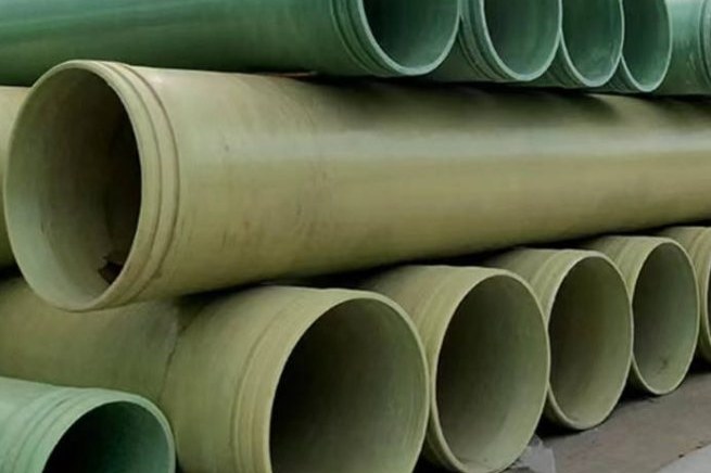
A pickling line in a stainless steel plant orders a new FRP storage tank for a mixed hydrofluoric and nitric acid bath. The quotation says vinyl ester resin, and vinyl ester is indeed the right resin family for a mineral acid. Eighteen months later the tank weeps through the shell, and a section cut from the wall shows clean glass fibres standing proud of the resin like bristles. The resin did its job. The reinforcement was the problem, and the reinforcement is what every standard FRP laminate is built from.
Hydrofluoric acid and its cousin fluorosilicic acid are the two service fluids where the normal selection logic stops working. For sulphuric, hydrochloric, nitric or acetic acid the question is which resin, and the answer is usually a vinyl ester or a dual laminate. For fluoride service the resin is almost secondary, because the acid attacks the glass itself. This guide works through the chemistry with numbers, the materials that actually survive, the barrier architecture that separates the acid from the structural laminate, the piping details that keep the barrier continuous, and the safety requirements that make the difference between a maintenance item and a fatality.
1. What Makes Fluoride Different from Every Other Acid
Glass fibre is a silicate. E-glass contains roughly 54 percent silicon dioxide, ECR glass around 60 percent, and both dissolve in hydrofluoric acid according to the reaction SiO2 + 4HF gives SiF4 + 2H2O. The silicon tetrafluoride leaves as a gas, and in the presence of more HF it forms fluorosilicic acid, H2SiF6. There is no glass grade that resists this reaction. Suppliers of corrosion-resistant glass are explicit about it: C-glass, ECR glass and boron-free E-glass are suitable for most chemical environments except those that attack glass, and hydrofluoric acid is the first example on the list.
The practical consequence is that a standard FRP laminate in fluoride service fails from the inside out. The resin matrix is attacked only slowly, but it is permeable. Acid reaches the first filament, dissolves it, and leaves a void that holds more acid and exposes the next filament. The laminate does not lose strength gradually across the whole wall; it loses the barrier, then the structural layer, and the visible sign is a white, chalky bloom or a soft patch that a knife can dig into. Once that has started, the pressure rating on the nameplate is meaningless, because the reinforcement that carried the hoop stress is gone.
For most acids the question is which resin. For fluoride the question is what stands between the acid and the glass, because no resin on its own will keep the acid away from the fibres forever.
The same chemistry applies outside the pipe or tank. Glass-filled PTFE gaskets, ceramic instrument diaphragms, glass rotameters, concrete containment, and even standard E-glass grating used as a walkway in the drip zone are all silicate-based and all attacked. A plant that gets the vessel right and the gaskets wrong has not solved the problem.
2. The Fluoride Streams You Will Actually Meet
Fluoride service is not one condition. The concentration determines how the acid behaves towards metals as well as towards glass, and the temperature determines the rate. The table below sets out the streams that appear most often in enquiries.
| Stream | Typical concentration and temperature | Behaviour that drives material choice |
|---|---|---|
| Aqueous hydrofluoric acid, dilute to medium | 10 to 49 percent HF, ambient to 50 C | The most aggressive case for glass and for most metals; low pH, high fluoride activity, attacks silica at any concentration |
| Concentrated hydrofluoric acid | 70 percent and above, ambient | Carbon steel can be used because a fluoride film passivates the surface; the same steel fails rapidly in dilute acid. Glass is still attacked. |
| Anhydrous hydrogen fluoride | Essentially 100 percent, under pressure | Handled in steel cylinders and specialised metallurgy; not an FRP application |
| Fluorosilicic acid | 20 to 25 percent H2SiF6, ambient to 40 C; density about 1.19 at 23 percent, 1.27 at 30 percent | Ships as a stable solution and is far less volatile than HF, but generates HF on heating, on dilution and on contact with bases; attacks silica, ceramics and concrete |
| Stainless pickling and passivation baths | 1 to 5 percent HF with 10 to 20 percent nitric acid, typically 20 to 50 C | Mixed acid with oxidiser; the nitric acid raises the corrosion potential and the HF removes the passive film and the glass |
| HF-bearing scrubber liquor and glass etch exhaust | Parts per million to a few percent, 40 to 80 C | Low concentration but often hot and aerated; condensate and droplets concentrate at the duct low points |
| Phosphate process streams | Fluoride with phosphoric and sulphuric acid, 60 to 90 C | Combined acid and fluoride attack plus scale; the temperature rules out most thermoplastics |
Two of these rows are routinely misread. The first is concentrated HF: the fact that carbon steel survives 70 percent acid does not make steel suitable for a 20 percent line, and it certainly does not make it suitable for a tank that is washed with water. The second is fluorosilicic acid: because it is a weaker, less volatile acid, it is often treated as a mild duty, but the fluoride is still there and the acid releases HF as soon as it is heated or neutralised.
3. The Chemistry in Numbers
Fluoride attack is one of the few corrosion problems that can be quantified from first principles, because the reaction is stoichiometric. One kilogram of silicon dioxide consumes 1.332 kg of HF. Using 54 percent SiO2 for E-glass, one kilogram of glass consumes 0.72 kg of HF. A 23 percent fluorosilicic acid solution contains 0.274 kg of H2SiF6 per litre, which is 1.900 mol and therefore carries the fluoride equivalent of 76 g of HF per litre. Dividing one by the other, one kilogram of glass needs about 9.5 litres of 23 percent fluorosilicic acid to be completely dissolved.
That number changes the way a barrier is specified. A corrosion barrier is not an impermeable membrane; it is a reservoir of glass that the acid will consume if it reaches it. The table below converts common barrier constructions into the volume of acid needed to strip the glass out of one square metre.
| Barrier construction | Thickness (mm) | Mass per m2 (kg) | Glass per m2 (kg at 30 percent) | Acid to dissolve the glass (L of 23 percent HFS per m2) |
|---|---|---|---|---|
| C-glass surface veil only | 0.5 | 1.0 | 0.23 | 2.2 |
| Veil plus one surface mat | 1.0 | 2.0 | 0.47 | 4.5 |
| Standard corrosion liner | 2.5 | 4.0 | 1.20 | 11.4 |
| Heavy-duty corrosion liner | 5.0 | 8.0 | 2.40 | 22.7 |
The comparison is blunt. A 200 litre spill, a sump that fills once, or a tank that is cleaned with a fluoride-containing detergent can deliver enough acid to consume the glass in an 18 square metre patch of a 2.5 mm liner. Thickening the barrier buys time but does not change the outcome, because the acid is replenished every time the tank is filled. This is why the only durable answer is a barrier that contains no silicate at all, and why the thickness of a glass-containing barrier is a maintenance interval rather than a design solution.
The same arithmetic is useful on the structural side. A 20 cubic metre tank, 2.6 m in diameter and 3.8 m high, with a 12 mm wall at 30 percent glass, contains about 950 kg of laminate and 285 kg of glass in its shell and ends. Dissolving all of that glass would take roughly 2,700 litres of 23 percent fluorosilicic acid. Nobody plans to do that, but a leak path that reaches the structural layer has a very large acid reservoir on the other side of it, and the dissolution front does not stop at the barrier.
4. Materials That Survive, and the Ones That Only Look Like They Do
There is no single "HF-resistant FRP". There is a family of constructions, each with a temperature ceiling and a failure mode. The table below is the selection matrix that should sit behind a quotation.
| Material | Fluoride resistance | Practical temperature ceiling | Where it fits and where it fails |
|---|---|---|---|
| E-glass / vinyl ester FRP | Not acceptable in contact with fluoride | Resin-limited, typically 80 to 100 C | Structural layer only, behind a non-silicate barrier. Never the wetted surface. |
| ECR glass / vinyl ester FRP | Better acid resistance than E-glass, still attacked by HF | Resin-limited | Improves general acid durability and strain corrosion, but does not make the glass HF-resistant. Still needs a barrier. |
| Carbon veil + vinyl ester barrier | Good: carbon contains no silica | Resin-limited, typically 100 to 120 C with a high-HDT vinyl ester | The standard upgrade for FRP equipment. The veil must be continuous and the resin must be fully cured; a porous veil is a path, not a barrier. |
| Polyester or PAN synthetic veil | Good: developed specifically for HF and caustic service | Resin-limited | Lower cost than carbon, less conductive, but poorer thermal conductivity and lower mechanical toughness; confirm the supplier's fluoride data. |
| Carbon fibre reinforcement | Excellent | Resin-limited | Used where the structure itself must be fluoride-proof, for example a small vessel with no liner. Expensive and galvanically incompatible with steel fittings. |
| PP and PP/FRP dual laminate | Excellent | About 100 C | Good for 20 to 30 percent acid at moderate temperature; the welded PP liner is the barrier and the FRP is only structure. |
| PVC and CPVC lining | Excellent | About 60 C for PVC, 90 to 95 C for CPVC | Low cost, good for ambient dilute acid; the welded seam quality decides the life. |
| PVDF and PVDF/FRP dual laminate | Excellent | About 120 to 140 C continuous | The default for hot HF and fluorosilicic acid; higher cost and a more demanding welding procedure. |
| ECTFE lining | Excellent | About 150 C | Used where oxidisers or chlorine are also present; higher cost than PVDF |
| PTFE | Excellent | About 200 C | Gaskets, diaphragms, valve seats and small parts; not a structural material |
| Carbon steel | Only above about 70 percent HF, by fluoride film passivation | Ambient | Concentrated acid storage; fails rapidly in dilute acid and in wet cycling |
| 316L stainless steel | Poor | Not recommended | Pitting and stress corrosion in dilute fluoride; not a fallback |
| Hastelloy C and Carpenter 20 | Good | Up to about 80 C | Wetted metal parts, instrument wetted parts, small valves; expensive |
Two entries deserve a note. ECR glass is often sold as the answer to acid service, and it is a genuine improvement for sulphuric and hydrochloric acid because it is boron-free and less soluble. It is not an answer to fluoride, because the attack is on the silica network itself, which ECR still has. And carbon veil is often described as "HF resistant" without qualification: the veil is resistant, but a veil of 30 to 50 grams per square metre is thin, and its protective value depends on it being resin-rich, continuous and fully wetted out. A dry spot in a carbon veil is a hole in the barrier.
5. Barrier Architecture: What Goes on the Wetted Surface
For a laminate that must handle fluoride, the barrier is a separate design from the structural wall, and it should be drawn as such. The sequence from the wetted surface outwards is: a resin-rich topcoat or gelcoat that contains no silica filler, one or two layers of carbon or synthetic veil, then a corrosion liner of chopped strand mat at high resin content, and only then the structural laminate. The liner is the part that provides thickness and redundancy; the veil is the part that provides the actual chemical barrier.
Thickness follows the duty. A 2.5 mm corrosion liner is the common minimum for chemical service and is adequate for ambient dilute acid. For hot acid, thermal cycling or a tank that will be cleaned mechanically, 4 to 6 mm is usual, and some specifications call for two veils separated by mat so that a pinhole in the first does not reach the glass behind it. The RTP-1 strain limits still apply to the barrier: 0.13 percent for sustained loads with a high-elongation resin, 0.10 percent for lower-elongation resins, and 0.20 percent for intermittent loads. Those limits exist to stop the barrier cracking in service, and a cracked barrier in fluoride service is a countdown, not a defect.
Fillers and pigments are part of the barrier, and this is where fluoride service catches out standard formulations. Calcium carbonate, glass microspheres, mica and most mineral fillers are silicate or carbonate based and will be attacked, leaving a porous resin layer. Specify a silica-free filler system, or a resin with no filler at all in the wetted layers, and confirm with the resin supplier that the pigment package is stable in fluoride. The same rule applies to the topcoat: a filled, coloured topcoat that looks good in a sample book may be the weakest layer in the tank.
Cure is the other half of the barrier. An under-cured vinyl ester has residual styrene, a low glass transition temperature and a higher permeability, and it will pass a visual inspection while failing in service. Post-cure according to the resin data sheet, verify with Barcol hardness and a acetone sensitivity check, and record the results. For a fluoride tank, a barrier that is 95 percent cured is not 95 percent as good; it is a different material.
6. Joints, Cut Edges and Penetrations: Where the Glass Gets Exposed
A continuous barrier over a cylinder is straightforward. The failures happen where the geometry changes, because those are the places where the laminate is cut, overlapped or finished by hand.
- Butt-and-strap joints. The overlay must rebuild the full barrier, not just the structural plies. That means veil, then mat, then structural layers, with the overlay tapered at 1:6 and the joint surface ground to fresh laminate before laminating. A joint that is structurally strong but has no veil in the overlay is a line of glass exposed to acid.
- Nozzles and manways. The barrier must run through the nozzle neck and turn onto the flange face. A common shortcut is to laminate the nozzle as a structural stub and then paint the inside with resin; that is a coating, not a barrier, and it will fail at the shell-to-nozzle knuckle where the strain is highest. Use a liner stub or a flanged spigot that carries the barrier to the gasket face.
- Field cuts and modifications. Every cut edge exposes chopped strand end-grain, which wicks acid by capillary action faster than the flat surface absorbs it. Seal cut edges with resin and a strip of veil, not resin alone.
- Flange faces. A machined FRP flange face can expose glass. Specify a resin-rich face or a liner that turns over the face, and use a full-face gasket so that the bolts compress the gasket against a sealed surface rather than against cut fibres.
- Supports and saddles. A steel saddle in contact with a fluoride-wet shell creates a crevice that holds acid and prevents inspection. Use a dielectric pad and a drainable detail, and inspect the shell under every saddle at each shutdown.
The structural laminate can be perfect and the equipment can still fail in a year, because the acid only needs one continuous path from the wetted surface to the first bundle of glass. Joints, cut edges and flange faces are where that path is created.
7. Piping-Specific Design: Rating, Temperature and Movement
For pipe, the fluoride problem is the same but the geometry makes it less forgiving. The wall is thinner, the surface-to-volume ratio is higher, and the consequences of a leak are usually worse because the line runs through a plant rather than sitting in a bund.
The first distinction to make on a datasheet is between the pressure rating and the chemical rating. A DN200 FRP pipe rated PN10 has that rating in water at a stated temperature, qualified by long-term hydrostatic testing to ASTM D2992 and dimensioned to ASTM D2996. None of that testing says anything about fluoride. The chemical resistance is a property of the barrier and is established by immersion testing to ASTM C581 and by the resin supplier's data at the actual concentration and temperature. A pipe can be perfectly rated for pressure and completely unsuitable for the fluid, and the two claims are often printed next to each other on the same submittal.
Temperature derating is the second issue. The pressure rating falls as the service temperature approaches the resin's heat deflection temperature, and the factor comes from the specific product's qualified data, not from a generic table. In fluoride service there is an extra reason to stay well below the limit: the same temperature that softens the resin also increases the permeability and the reaction rate, so the barrier degrades faster exactly when the structure is weaker. A line that is marginal at 60 C in water is not marginal at 60 C in 20 percent HF; it is unacceptable.
Movement is the third. A wound FRP pipe has a longitudinal coefficient of thermal expansion of roughly 2.4 x 10^-5 per kelvin, so a 20 m run moving through 40 K grows by 19.2 mm, and a 30 m run through 60 K grows by 43.2 mm. Fluoride lines are often traced, insulated or cleaned with hot water, so the movement is real. The pipe needs guides that keep it straight without clamping it, anchors that take the thrust at changes of direction, and expansion loops or compensators where the run is long. A line that is clamped rigidly at both ends will transfer the movement into the flange bolts and the nozzle, and a cracked flange face in fluoride service is a leak that cannot be repaired in place.
Component selection follows the same logic as the vessel. Lined butterfly valves with a PTFE seat and a virgin PTFE liner, diaphragm valves with a PTFE diaphragm, and full-face PTFE-envelope gaskets are the default. Avoid glass-filled PTFE seats and gaskets, which are common in general chemical service and are attacked by fluoride at the exposed glass. Avoid 316L wetted parts, including instrument bodies and small fittings, unless the supplier can show fluoride data at the service temperature.
8. Instrumentation, Gaskets and Secondary Containment
Instrumentation is the most frequent source of unplanned fluoride exposure, because instruments are bought by a different team, from a different catalogue, with a general-purpose chemical rating. Three rules cover most of the problem.
First, no glass or ceramic in contact with the fluid. Glass rotameters, ceramic pressure sensor diaphragms, glass-filled plastic bodies and sight glasses are all silicate and all attacked. Use a PTFE or PVDF diaphragm seal on pressure transmitters, a non-contact level technology such as radar or ultrasonic, and a PTFE-lined or PVDF-bodied flow element. Second, no glass-filled wetted parts anywhere in the assembly, including the small fittings that nobody specifies. Third, bring the instrument connection out of the tank or pipe with a lined stub so that the barrier is continuous to the instrument flange.
Secondary containment needs the same treatment. Concrete is a silicate material and is attacked by fluoride, so a bund lined with an ordinary epoxy coating will fail; the lining has to be a fluoride-rated system such as a PVDF sheet, a PP liner or an acid-resistant brick with a membrane. The bund should be sized for the largest vessel plus a margin, drainable, and connected to a neutralisation sump. For fluorosilicic acid, one litre of 23 percent solution needs about 0.28 kg of hydrated lime for complete precipitation as calcium fluoride, so a 200 litre spill requires roughly 56 kg of lime, and a 1 m3 spill about 281 kg. A spill kit with two bags of lime is not adequate for a bulk tank.
Detection and first aid belong in the same paragraph because they are the same system. Fit fluoride or HF vapour detection at the low points and at the bund, with the alarm set well below the occupational limit, and make sure the eyewash and safety shower are reachable within ten seconds from the unloading point. Delayed symptoms are the reason this matters: dilute HF can be painless for hours, and a worker who feels nothing after a splash may still be developing a systemic fluoride exposure.
9. Quality Control: Coupons, Thickness and Spark Testing
Fluoride service punishes assumptions, so the quality plan has to produce evidence for the three things that matter: the barrier is the specified material, it is the specified thickness, and it has no holes.
| Check | Method | What it proves |
|---|---|---|
| Barrier composition | Laminate coupon and resin burn-off to ASTM D2584, plus a supplier certificate for the veil type | That the veil is carbon or synthetic, not C-glass, and that the resin is the specified grade |
| Barrier thickness | Ultrasonic thickness on the finished part, plus a destructively sectioned coupon from the same run | That the liner is 2.5 mm or 5 mm as specified, rather than the 1.5 mm that hand laminating often produces |
| Cure | Barcol hardness to ASTM D2583, compared with the manufacturer's minimum, and a post-cure record | That the resin has reached its specified glass transition and permeability |
| Chemical resistance | Immersion coupons to ASTM C581 at the service concentration and temperature, read at 3 and 12 months | That the laminate retains its properties in the actual fluid. The standard gives the method, not a pass mark, so write the acceptance criterion into the specification before the test. |
| Holiday detection | High-voltage spark test over the wetted surface of a thermoplastic lining, at the voltage specified for the lining thickness | That a dual laminate has no pinholes or weld defects through the liner |
| Joint integrity | Visual and tap inspection of every overlay, plus a spark test where the barrier is thermoplastic | That the barrier is continuous through joints, nozzles and flange faces |
| Pressure test | Hydrotest with chloride-free water, at the pressure and hold time in the purchase specification | That the structural wall is sound. It does not prove the barrier, which is why the checks above come first. |
The coupon test is the one that gets dropped when a project is late. It should not be, because it is the only direct evidence that the laminate will survive the fluid. Make the coupons from the same resin batch, the same veil and the same cure as the production laminate, expose them at the service temperature rather than at room temperature, and keep one set unexposed as a baseline. A supplier who cannot produce a 12-month coupon programme for a fluoride duty is offering an opinion rather than a qualification.
10. Safety: The Part That Is Not About Materials
Hydrogen fluoride is a contact poison as much as a corrosive. The fluoride ion penetrates skin, binds calcium and magnesium in tissue, and can cause systemic hypocalcaemia and cardiac arrhythmia from a burn that looks small. The occupational limits reflect that.
| Parameter | Value | Source |
|---|---|---|
| OSHA permissible exposure limit, HF | 3 ppm as an 8-hour time-weighted average | 29 CFR 1910.1000 |
| NIOSH recommended exposure limit | 3 ppm TWA, 6 ppm ceiling for 15 minutes | NIOSH REL |
| NIOSH immediately dangerous to life or health | 30 ppm | NIOSH IDLH |
| ACGIH threshold limit value | 0.5 ppm TWA, 2 ppm ceiling | ACGIH TLV |
| OSHA limit for fluorides as F | 2.5 mg/m3 | 29 CFR 1910.1000 |
| First aid for skin contact | Flush with water for at least 30 minutes, apply 2.5 percent calcium gluconate gel, get medical attention | Standard HF first-aid practice; the SDS and the site EHS procedure govern |
Three operational rules follow from the chemistry rather than from a regulation. Do not use sand, clay or any silica-based absorbent on a fluoride spill, because the absorbent will react and release silicon tetrafluoride; use an inert absorbent and neutralise with a calcium-based agent. Do not store or sample fluoride in glass, ceramic or concrete, including glass sample bottles and ceramic laboratory ware. And do not put nitrile gloves on a 30 percent or stronger HF exposure; the glove selection tables call for butyl, neoprene or a laminate film for concentrated acid, with nitrile acceptable only for brief contact with dilute solutions.
The material selection and the safety case meet at the inspection interval. A fluoride plant should inspect its FRP equipment for barrier damage at every shutdown, not only when there is a leak, because the first visible sign of barrier failure is a white bloom or a soft patch, and the equipment is still holding pressure at that point. Thickness readings on the wetted surface, a tap test around every nozzle and a visual check of every joint will find the problem while it is still a repair.
Specify the Barrier, Not Just the Resin
A fluoride enquiry that says "vinyl ester FRP" will get a quotation for a laminate that is correct in every respect except the one that matters. The specification needs to name the veil, the barrier thickness, the filler restriction, the cure requirement, the joint detail and the coupon test. With those six items written down, the material selection becomes auditable, and the difference between a ten-year tank and an eighteen-month tank stops being a matter of luck.
For the piping side, the wound process pipe range is here: custom filament-wound FRP/GRP process pipe, with the pressure pipe range at FRP pressure pipe, the flanges and fittings at FRP flange and pipe fittings and the water pipe range at FRP water pipe.
Related reading: resin selection for chemical equipment for the resin families behind the barrier, dual laminate liner selection for PP, PVC and PVDF compared, wet chlorine and chlor-alkali service for the other halogen duty that limits resin choice, hydrotest water quality for what the test fluid does to the laminate, pipe installation and pressure testing for jointing and field acceptance, flange and fitting ratings for the bolted connections, and manifolds and header laterals for the layout details that keep a header drainable.
Need help selecting FRP products?
Our engineers answer technical questions free of charge.
Ask an Engineer on WhatsApp