
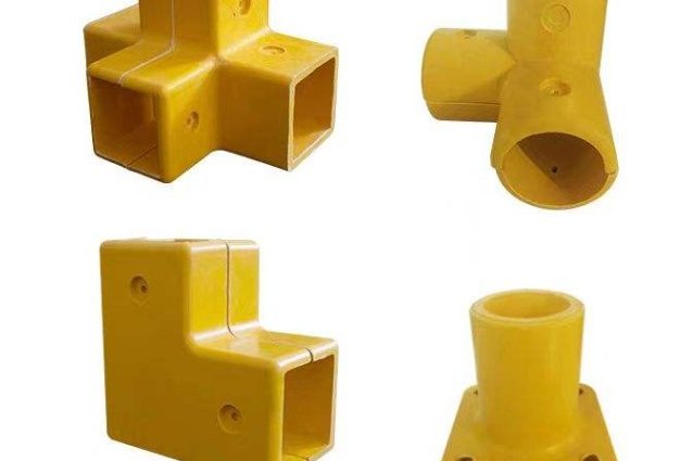
An FRP manifold is one of the few parts of a water or wastewater plant where a fabrication detail determines a process outcome. A header feeding a bank of laterals looks like plumbing, and it is priced like plumbing, but its job is to divide a single flow into twenty or more equal streams and to collect them back again without letting one lateral take twice the share of another. Get the header diameter wrong and the distribution across a filter bed or a membrane bank is uneven by ten per cent or more, which shows up months later as premature breakthrough on one side of the bed and a backwash that never quite cleans the other. This guide covers the manifold configurations and what each one is worth, why the far laterals in a dividing manifold receive more flow rather than less, a 100 cubic metre per hour example showing how header diameter controls the spread, and the fabrication and support details that decide whether the system still performs after two years in service.
1. What a Header and Lateral System Has to Do
A manifold is a junction assembly that divides or collects flow. In FRP it is normally built from the same pipe and fittings as the rest of the line, which means it inherits the corrosion resistance and the light weight and, just as importantly, the same coefficient of expansion and the same jointing method. Five functions have to be satisfied at once:
- Divide or collect the flow evenly. The spread between the best and worst lateral is the number that matters, not the mean.
- Keep the pressure drop low enough that the distribution does not depend on it. A manifold whose own loss is a large fraction of the available head cannot distribute evenly, no matter how it is detailed.
- Retain the media. Where the laterals sit under a sand, carbon or resin bed, the slots or strainers have to pass water and hold the bed.
- Survive handling and installation. A long header with twenty stubs is the most fragile thing on the site until it is finally supported, and it is usually the largest single piece in the shipment.
- Be inspectable and cleanable. Slots block, strainers break, and the design either allows access or converts a maintenance task into a re-bedding project.
2. Configurations and What Each One Is Worth
The choice of configuration is a direct function of vessel diameter. Below a certain size the laterals in a hub-and-radial arrangement are close enough together that the spacing does not matter; above it they are not.
| Configuration | Description | Distribution quality | Where it is right |
|---|---|---|---|
| Inverted H | Flow directed off the upper head, no laterals | Poor as a backwash collector | Small commercial filters only; the lowest-cost option |
| Hub and radial | Central hub with radial laterals, bicycle-wheel layout | Good | Vessels up to about 1500 mm diameter |
| Header and lateral | Central or offset header with laterals reaching the sidewall | Best | All sizes; the standard for anything above 1500 mm |
| Header with dropped laterals | Header with laterals extending into the dished bottom | Good, with a caveat | Where the bottom head volume must be used as bed; particles can collect and resist backwashing |
| Basket strainer on a riser | Single strainer screwed into the head | Adequate for small resin vessels | Vessels with no manway to install anything larger |
| Header as a one-piece block | Monolithic pultruded or moulded block with drilled ports | Best, and no joints to leak | High-pressure or high-cycle service where every joint is a liability |
Two practical points fall out of that table. The first is that the header-lateral configuration costs more than the hub-radial one, and the premium is real, but it is a fraction of the cost of re-bedding a filter because one half of the bed was never properly backwashed. The second is that the one-piece block eliminates the joint between header and branch, which is where a manifold leaks. Where the pressure is high enough that a leaking joint is a safety issue rather than a nuisance, the block is the answer.
3. Why the Far Laterals Get More Flow
The intuitive expectation is that friction along the header starves the far end, so the last lateral gets less. For a dividing manifold — one with an inlet at one end and take-offs along its length — the opposite is usually true, and understanding why is the key to designing one.
As flow is drawn off along the header, the velocity in the header falls. Falling velocity means the velocity head, the kinetic energy term, is being converted back into static pressure. That recovery competes with the friction loss along the same length. For a manifold of ordinary proportions the recovery wins:
- The velocity head at the inlet is v2 / 2g, and it is released progressively along the header.
- The friction loss, with flow falling linearly to zero at the closed end, is only about one third of what the same length would lose at full flow throughout.
- The net change in static pressure from the first lateral to the last is therefore friction divided by three, minus the full inlet velocity head.
- When that number is negative, the static pressure rises toward the closed end and the last lateral discharges more than the first.
The design variable that controls the flow split in a dividing manifold is not the friction loss, it is the velocity head in the header. Making the header smaller increases the friction loss and also increases the velocity head, and the velocity head is the larger of the two effects. Header sizing is a distribution decision, not a pressure-drop decision.
4. Worked Example: 100 Cubic Metres per Hour Over 24 Laterals
Take a filter underdrain with a 3 metre long header feeding 24 evenly spaced laterals of 25 mm bore, carrying 100 cubic metres per hour, with 5 metres of driving head available at the first lateral. The header diameter is the variable.
| Header | Velocity | Velocity head | Friction, full flow | Friction, average | Net change at the far end | Last/first flow ratio |
|---|---|---|---|---|---|---|
| DN150 | 1.57 m/s | 0.126 m | 0.050 m | 0.017 m | minus 0.109 m | 1.011 |
| DN100 | 3.54 m/s | 0.638 m | 0.383 m | 0.128 m | minus 0.510 m | 1.050 |
| DN80 | 5.53 m/s | 1.557 m | 1.167 m | 0.389 m | minus 1.167 m | 1.111 |
The negative sign means the static pressure rises toward the closed end, so the far laterals discharge more. Translated into flow and spread:
| Header | First lateral | Last lateral | Spread | Velocity in the lateral |
|---|---|---|---|---|
| DN150 | 4.14 m3/h | 4.19 m3/h | 1.1 per cent | 2.37 m/s |
| DN100 | 4.07 m3/h | 4.27 m3/h | 5.0 per cent | 2.42 m/s |
| DN80 | 3.95 m3/h | 4.39 m3/h | 11.1 per cent | 2.48 m/s |
Three conclusions follow. A DN150 header holds the spread inside about one per cent, which is better than most process requirements. Dropping to DN80, which would be a defensible choice on a pressure-drop calculation alone, produces an eleven per cent spread across the bed — enough to matter for media exhaustion and for backwash effectiveness. And the velocity through the laterals barely changes between the three cases, because the driving head is dominated by the downstream bed loss rather than by the manifold. The laterals are not the problem; the header is.
Where a single header cannot be made large enough — usually because of space or because the nozzle into the vessel is fixed — the header can be stepped or tapered, so that the second half runs at a smaller diameter and the velocity is held roughly constant along the length. That removes the velocity-head recovery as a source of imbalance. Stepping a DN150 down to a DN100 for the second half holds the velocity within about 13 per cent of constant, and stepping DN100 to DN80 within about 22 per cent, which is a large improvement on the 60 per cent rise that a full-length constant diameter gives.
5. Slots, Strainers and Media Retention
Where the laterals sit inside a bed, the openings are what determines whether the system works. The design variables are the slot width, the slot area per unit length, and the resulting velocity at the slot.
- Slot width: conventionally 0.2 to 0.5 mm, chosen against the smallest particle that must be retained. Too fine and the slots block with fines; too coarse and the bed migrates into the manifold.
- Open area: the total slot area has to be several times the lateral bore area, so the slot velocity stays low enough not to fluidise the adjacent bed locally.
- Backwash direction: slots that pass water in one direction and retain media in the other have to be symmetric in area, otherwise the backwash pressure drop is far higher than the service drop.
- Accessibility: a lateral that cannot be removed and cleaned individually turns a blocked slot into a full bed replacement.
Where media retention is critical, a gravel or garnet support layer under the bed, or a graded support arrangement, does more for longevity than any refinement of the slot pattern. The laterals are there to distribute and collect, not to carry the media.
6. Fabrication: Where the Manifold Is Won or Lost
A manifold is a fabrication, and the fabrication is what determines whether the hydraulic design is realised. Four details carry most of the risk:
- Branch joints. Every stub is a saddle or a tee, and every one is a stress concentration. The joint has to be built up with the same laminate as the pipe, with the build-up extending a proper distance up the branch and along the run, and with the layers continued rather than merely thickened.
- Cut edges. Where a stub is cut into a header, the exposed glass at the cut is the entry point for any chemical attack. Each cut edge needs sealing with a resin-rich build-up before the joint laminate goes on.
- Port alignment. In a one-piece block, the ports are drilled and the alignment of twenty ports is set by the drilling jig, not by the fabricator's eye. In a built-up header, alignment is set by how the stubs were tacked, and small errors accumulate into laterals that will not fit the supporting grid.
- Liner continuity. Where a liner is used at all, it has to be continuous through the branch. A liner that stops at the run and leaves the branch in structural laminate is a barrier with a hole in it, and the hole is at the point of highest turbulence.
On pressure and testing: a manifold should be hydrostatically tested as an assembly at 1.5 times the operating pressure, because the joints are the parts that have not been proven by the pipe's own test. For atmospheric underdrains, a water fill and a visual check of every joint plus a distribution test on site is the practical equivalent.
7. Support and Handling
The manifold is the largest, lightest and least stiff item on most installations, which makes it the one most likely to be damaged before it is commissioned. The support scheme is part of the design.
- Support at the joints, not between them. A concentrated branch load applied between supports turns into a local bending moment at the run.
- Support the assembly, not the vessel. An underdrain hung from the tank shell loads the shell; an underdrain standing on the bottom transmits a point load into the bottom laminate. Neither is automatically wrong, but each needs to have been considered.
- Allow for movement. FRP expands and contracts about two to three times as much as steel for the same temperature change. A long header fixed at both ends and restrained by piping will find the weakest joint.
- Lift it properly. Sling at the header, in at least two places, and never lift by a lateral. A lateral bent during handling is a lateral that will not distribute correctly and will not be easy to identify as the cause.
- Integral supports are worth asking for. Suppliers can attach saddles or brackets to the header during fabrication, which distributes the load over the shell rather than concentrating it and simplifies alignment on site.
8. Commissioning and Start-Up
A manifold should be proved by measuring, not by looking. The distribution test is straightforward and it is worth insisting on:
- Fill and backwash with clean water before any media is placed, and check that every lateral discharges and that none is blocked by fabrication debris.
- Measure the flow from each lateral individually, by collecting and timing. A spread of more than five per cent across the bank is worth investigating before the media goes in, because after it goes in you can no longer see the problem.
- Record the differential pressure across the manifold at design flow. That number is the baseline for every future condition assessment.
- Check the media retention after the first backwash, particularly around the vessel wall where the spacing between the last lateral and the shell is largest.
9. FAQ
Should the header be sized on pressure drop or on distribution? Distribution. Pressure drop is a cost question and it can be answered after the fact; distribution is a performance question and it cannot be corrected once the manifold is fabricated.
Is a hub-and-radial manifold ever better than a header? It is simpler, shorter, cheaper and easier to support. Below about 1500 mm vessel diameter it is often the better engineering choice, because the lateral spacing at that size is small enough that distribution is not compromised.
What causes a manifold to perform badly after a few years? Media migration into the slots, scale or biological growth in the laterals, and failure of a support or an anchorage that lets the assembly sag. Only the third is a structural issue, and it is the one that is easiest to miss visually.
How much does the one-piece block cost compared with a built-up header? It is usually more expensive per assembly, because the tooling and the machining are extensive. It justifies itself where the pressure is high, where the cycle frequency is high, or where a joint failure would release a hazardous fluid.
Do the lateral bores all have to be the same? No, and in some designs they deliberately are not. Making the laterals slightly smaller toward the closed end of an equalising header can offset the pressure recovery, but it makes fabrication and replacement harder, and changing the header diameter is usually the better lever.
10. Designing a Manifold That Distributes Properly
At Henan HuanGang we fabricate filament-wound FRP and GRP pipe and manifold assemblies for process and water service, including headers with wrapped branch joints, one-piece drilled blocks and integral supports. Send us the total flow, the vessel diameter, the number of laterals and the available head, and we will come back with the header diameter, the lateral bore and the expected spread across the bank — and if a single-diameter header cannot hold the spread inside your tolerance, we will say so and propose a stepped arrangement rather than quoting something that will not perform. If you are replacing a manifold that has not distributed properly in service, tell us what you saw: the pattern of the problem usually identifies the cause.
Related reading: GRP pipe specification and selection, FRP pipe diameter and wall thickness, FRP pipe support spacing and hanger design, GRP pipe bedding, backfill and ring deflection, long-term hydrostatic strength of GRP pipe, FRP flange and fittings ratings, FRP pipe installation and pressure testing and FRP profiles in wastewater treatment.
Need help selecting FRP products?
Our engineers answer technical questions free of charge.
Ask an Engineer on WhatsApp