
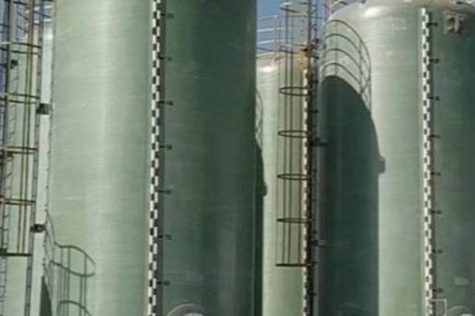
Chlorine is the one process chemical where the answer to "which material" flips inside a single specification limit. Below roughly 150 ppm of water, chlorine is non-corrosive to ordinary carbon steel and is handled in it worldwide. Above that line the same gas attacks that steel at rates that perforate pipe walls in under a year, while a different family of materials - titanium and fluoropolymers - becomes usable. FRP straddles that line in a way that surprises people: it is the default material for a large share of a chlor-alkali plant, and it is the wrong material for one specific duty in the same plant.
This guide sets out where FRP belongs in a chlorine or chlor-alkali circuit, what limits the resin and the liner, and how to specify and inspect equipment that will see wet chlorine, hypochlorite, hot caustic and brine. The worked figures come from a calculation script so the arithmetic can be checked line by line, and the anchors point to the relevant equipment, such as our filament-wound FRP tank for HCl and chemical mixing service and our filament-wound FRP process pipe.
1. The 150 ppm Line That Decides the Material
Dry and wet chlorine are not two products; they are two moisture brackets of the same product. The convention used across the industry, and written into the material-selection guidance published by the Chlorine Institute, is that chlorine containing less than about 150 ppm of water behaves as dry, and anything above it behaves as wet. The mechanism is a protective film. On carbon steel, dry chlorine forms a ferric chloride layer that passivates the surface and stops further attack. Introduce moisture and chlorine hydrolyses to hydrochloric and hypochlorous acid, the film is undermined, and the wall starts to lose metal.
The arithmetic explains why such a small moisture figure carries so much weight:
| Water content of the chlorine (ppm by mass) | Water per kg of chlorine | Acid potential (HCl + HOCl) per kg of chlorine |
|---|---|---|
| 150 (the dry / wet convention) | 0.150 g | 0.74 g |
| 500 | 0.500 g | 2.47 g |
| 1,000 (0.1 %) | 1.000 g | 4.94 g |
| 10,000 (1 %) | 10.0 g | 49.4 g |
The ratio is fixed by stoichiometry: one mole of water produces one mole of HCl and one mole of HOCl, so each gram of water carries 4.94 g of acid potential. At the 150 ppm convention that is 0.74 g of acid per kilogram of chlorine - small, but distributed as a liquid film on the wetted surface rather than diluted in a bulk liquid, which is why local attack is severe even when the bulk assay looks acceptable.
There is a second reason the 150 ppm figure is quoted with a purge specification rather than as a bulk limit. A dew point of −40 °C, the value commonly required for purge air or nitrogen before breaking a dry-chlorine connection, corresponds to about 127 ppmv of water if the reference is saturation over ice, and about 189 ppmv if the reference is supercooled water. Both numbers sit either side of the 150 ppm convention, which is precisely why the purge specification and the material limit have to be read together. Ambient moisture ingress during a valve changeout can create a local wet condition on a surface that the bulk assay says is dry.
The practical rule for anyone specifying FRP in a chlorine plant: the dry side of the plant is a metal world, and the wet side is a materials world. FRP is a wet-side material. It is used for the wet chlorine headers, brine circuits, acid and hypochlorite duties - not for dried chlorine gas or liquid chlorine.
2. Why Titanium Is the Mirror Image of Steel
If you only remember one fact from a chlorine materials review, remember that titanium and carbon steel are resistant under exactly opposite conditions.
- Wet chlorine: titanium's passive titanium-dioxide film needs moisture to remain stable, so titanium is excellent in wet chlorine, chloride brine and hypochlorite. Carbon steel is destroyed.
- Dry chlorine: titanium reacts exothermically with dry chlorine and can initiate a metal fire. Carbon steel is the standard material.
This inversion has caused real releases. A documented case history describes a gauge with a titanium housing and a tantalum diaphragm being pulled from a storeroom and fitted to dry chlorine service because it looked like the stainless gauges normally used there; the exothermic reaction between the titanium and dry chlorine is believed to have started the metal fire that led to the chlorine release. If your specification lists materials by appearance or by a generic "chlorine service" label, that failure mode is still available to you.
The numbers that make the wet side unforgiving:
| Item | Value | Consequence |
|---|---|---|
| Published carbon steel corrosion rate in wet chlorine | over 7 mm per year | A 6 mm wall reaches perforation in about 10 months - the wall is gone before the first annual inspection |
| Ferric chloride film stability | breaks down above roughly 149 °C | Dry chlorine service has a temperature ceiling as well as a moisture ceiling; above it a chlorine-iron fire becomes possible |
| Chlorine liquid vapour pressure | 6.8 bar at 20 °C, 9.4 bar at 30 °C, 12.6 bar at 40 °C | A warm day raises the driving pressure for leaks in a system whose material limits are already exhausted |
| Titanium dioxide film breakdown | about 11.5 V anodic potential | In electrolysis cell rooms, stray current can drive a titanium component past this value; titanium then crevice-corrodes near welds and gaskets |
Note the last row. Titanium is often presented as the universal answer for chlorine, and it is not: it suffers crevice corrosion in gasketed joints and near welds in brine service, and it corrodes in chlorine dioxide applications where the chemistry has to be handled with titanium rings coated in mixed metal oxides to keep the surface in the passive region. Cost and availability push most of the plant back to composites.
3. Where FRP Is the Default Material in a Chlor-Alkali Plant
The scale of FRP's role is routinely underestimated. Industry surveys put GRP and GRE at roughly 80 % of the piping and equipment in a chlor-alkali plant. That is not a niche role in a corrosion problem; it is the plant's primary structural material for fluids.
The reason is that a cell room presents four or five different corrosion problems at once, and the composite can be tuned to each of them with resin and liner selection rather than by changing the metal.
| Stream | Typical conditions | Usual FRP construction | The dominant risk |
|---|---|---|---|
| Concentrated sodium chloride brine | Ambient to warm; near-saturated | Bisphenol-A vinyl ester, resin-rich barrier | Chloride attack on any metallic component; leaching of ions that poison the membrane cell |
| Depleted / outlet brine | Warm, high pH in membrane plants | Vinyl ester, thicker barrier | Combined high pH plus temperature; documented cases of FRP piping needing replacement after a short service life in warm outlet brine |
| Wet chlorine gas from the cells | Warm; moisture well above 150 ppm | Resin-rich FRP header; historically bisphenol-A vinyl ester grades such as Hetron 197-3, brominated vinyl ester such as 998-35, or Derakane 510N | Oxidation of the resin matrix; the corrosion barrier is the whole design |
| Hydrochloric acid 31-33 % | Ambient to 50 °C | Vinyl ester or dual laminate | Concentration and temperature together; above roughly 35 % the reliable resin window narrows |
| Sodium hydroxide 32-50 % | Up to and beyond 80 °C in the hot leg | Dual laminate or low-ester-bond vinyl ester | Ester hydrolysis and saponification; hot concentrated caustic is the hardest duty in the plant |
| Sodium hypochlorite | Ambient, alkaline, oxygen-evolving | Vinyl ester or fluoropolymer-lined | Oxidation plus the fact that the product is decaying while it is stored |
| Chlorine dioxide (where the plant makes it) | Acidic, oxidising | Vinyl ester with an oversized barrier; fluoropolymer liner in severe service | Uniform attack that consumes the corrosion barrier; service life is a matter of barrier thickness |
Two practical notes on that table. First, the stream that most often defeats FRP is not the exotic one: it is warm caustic or warm high-pH brine, because both the ester bonds in the resin and the chloride environment are working at the same time. Second, chlorine headers built in Europe are increasingly dual laminate with a chlorinated PVC liner rather than all-FRP. A published comparison of the two constructions gives a service life of 8 to 10 years for the CPVC/FRP dual laminate header against 6 to 12 years for all-FRP at comparable cost - the same order of life, different failure modes, and a different position on the fire and stray-current question.
4. Resin Selection: Three Families, Three Temperature Ceilings
Resin choice in a chlorine plant is decided by three things in order: oxidising strength of the medium, temperature, and the presence of alkali. The resin families sort cleanly.
| Resin family | Heat distortion temperature | Practical service ceiling at HDT − 22 K | Where it fits, and where it does not |
|---|---|---|---|
| Isophthalic polyester (ISO-UPR) | 80-90 °C | 58-68 °C | Brine, dilute neutral solutions, atmospheric water. Struggles with caustic above pH 10, with oxidising acids and with chlorinated solvents |
| Bisphenol-A epoxy vinyl ester | 100-110 °C | 78-88 °C | The workhorse for wet chlorine headers, hypochlorite and hot acid. Published resistance to 70 % sulphuric, 30 % hydrochloric, sodium hypochlorite and ferric chloride to about 80 °C |
| Novolac (epoxy novolac) vinyl ester | 130-150 °C | 108-128 °C | Extended into hot oxidising and hot bleach lines, to roughly 110-120 °C in published guidance. The standard choice for the hot end of a chlor-alkali circuit |
The reason vinyl ester outperforms polyester in this service is structural, not marketing. Vinyl ester's backbone is a polyester chain capped with methacrylate end groups, which leaves far fewer ester linkages exposed to hydrolysis - the reaction that oxidising media accelerate. Vinyl ester also shows 30 to 50 % higher elongation at break than isophthalic polyester, which translates into better fatigue and impact tolerance in equipment that is thermally cycled.
One resin family should be treated with suspicion here. Amine-cured epoxy is an excellent material for caustic and for solvents, but amine chemistry and chlorine do not coexist well: amine-based additives are incompatible with liquid chlorine service because of exothermic attack or chloramine formation. Where caustic duty in a chlorine plant calls for epoxy, verify the curing system and keep it away from the chlorine-bearing streams.
Cost logic works against you if you economise on the wrong layer. A hybrid lay-up - vinyl ester or novolac vinyl ester for the corrosion barrier and the first structural ply, cheaper isophthalic polyester for the bulk structural laminate behind it - is normal commercial practice and is defensible. Using the cheap resin in the barrier is not.
5. The Corrosion Barrier Is the Design, Not an Extra
In a chemical duty, the structural laminate never sees the chemical. A resin-rich barrier of roughly 2.5 mm - synthetic veil plus chopped strand mat, over-cured, with a high resin fraction - is what stands between the medium and the load-bearing fibres. Everything about the useful life of the equipment follows from that layer.
- Post-cure is mandatory, not optional. Above about 80 °C service, a room-temperature-cured laminate will continue to cure in situ, shrink and micro-crack. Post-cure at a temperature above the service temperature is what makes the barrier chemically stable.
- Cure state is measurable. Barcol hardness per ASTM D2583 is the field proxy. The acceptance criterion is a percentage of the resin manufacturer's published minimum, measured on a known-good reference coupon, not an absolute number.
- Immersion data is the only credible evidence. ASTM C581 immersion of laminate coupons in the actual medium, at the actual concentration and the maximum service temperature, for months, is the only evidence that matters. A brochure "chemical resistance" table is a starting point, not data.
For chlorine dioxide service the barrier has to be sized rather than assumed. The published corrosion model for FRP in ClO2 is a semi-empirical power law of the form
Φ = B · tα · c · A · e−Ea/RT
where Φ is the depth of corrosion in millimetres, t is service time in years, c is the chlorine dioxide concentration, A is a material constant depending on the resin, cure state and laminate structure, and the exponent α lies between 0.5 and 1 depending on the thickness and degradation state of the attacked surface layer. B is 1 with no protective deposit and 0 if a surface deposit gives complete protection.
The engineering value of that expression is the sensitivity, not the absolute prediction. If a coupon from an existing unit shows 1 mm of uniform loss in 5 years and the barrier is fully consumed at 2.5 mm, the extrapolated life is:
| Exponent α | Extrapolated life to full barrier consumption | Effect of doubling the barrier thickness |
|---|---|---|
| 0.5 (attack strongly diffusion-limited) | 31 years | 4.0 × |
| 0.75 (typical) | 17 years | 2.5 × |
| 1.0 (linear, surface-controlled) | 12.5 years | 2.0 × |
That is the argument for specifying an oversized barrier on oxidising duties rather than accepting a nominal one. It is also the argument for taking a destructive plug or an ultrasonic thickness reading from a sacrificial area at every major shutdown, because the actual α for your resin, cure and temperature is what governs, and it cannot be read from a datasheet.
6. Temperature, Not Concentration, Usually Kills the Laminate
Chlor-alkali streams are hot. Liquids and gases around 104 °C (220 °F) are described as common in published plant surveys, and that single fact eliminates isophthalic polyester from most of the circuit and puts standard bisphenol-A vinyl ester at the top of its envelope.
Published construction practice for wet chlorine service in chlor-alkali plants reflects the same ranking:
| Wet chlorine service condition | Construction normally used | Why |
|---|---|---|
| Below about 80 °C | FRP with a bisphenol-A vinyl ester barrier and liner | Within the vinyl ester envelope with margin at the barrier |
| Below about 50 °C, low pressure | PVC or PVC-lined FRP | Cheaper and easier to fabricate at low temperature; the temperature ceiling is the limit, not the chemistry |
| Near 100 °C, with excursions to about 120 °C for 30 minutes or less | FRP with a novolac vinyl ester barrier | Needs the higher heat distortion temperature and the higher crosslink density of the novolac backbone |
| Sustained above roughly 120 °C | High-crosslink-density vinyl ester, fluoropolymer liner or a metal | Thermoset resin systems run out of ceiling; the problem becomes a liner or alloy problem |
Two design details turn a comfortable margin into a failure. The first is heat tracing or insulation applied to a line that was sized for ambient operation: a trace-heated hypochlorite or acid line can easily operate 20 to 30 K above the temperature the barrier was qualified at, and the resin does not know the difference between process heat and tracing heat. The second is thermal shock - a cold wash-down or a tanker discharge into warm equipment produces a through-thickness strain gradient that a resin-rich barrier tolerates less well than the structural laminate.
7. Caustic and Brine: The pH Side of the Plant
Resin selection for alkali is not the mirror of acid selection, and the failure mechanism is different again. In strong alkali the ester linkages in the resin hydrolyse and the surface saponifies, softening and eventually washing away; the barrier goes first and the fibres follow.
Rules that survive contact with the plant:
- Below about 60 °C, dilute and moderate caustic is handled well by PVC-lined FRP dual laminate. Cheap, welded, and repairable.
- Around 70 °C and above, the preference shifts to all-vinyl-ester FRP, and specifically to grades with a low ester linkage content. Choosing a vinyl ester by price rather than by ester content is the single most common cause of premature caustic failure in composite equipment.
- 40 to 80 °C caustic is the contested band. PVC-lined laminate and all-vinyl-ester FRP both work; which one is specified depends on how the designer weights thermal shock, repairability and stray current.
- Epoxy is a legitimate alternative for caustic - amine-cured epoxy tanks are used up to 50 % NaOH at 90 °C - but keep it out of any stream that carries chlorine, chlorine dioxide or hypochlorite, where epoxy systems are attacked by the oxidiser.
High pH plus temperature plus brine is a combination worth calling out separately, because it has a documented record of shortening FRP life in membrane-cell chlorine plants: FRP piping in warm outlet brine has had to be replaced after a short service period specifically because of the elevated pH. If your only inhibitor is resin family and you have not temperature-corrected it, this is the case that will expose the gap.
8. Sodium Hypochlorite: A Storage Discipline, Not Just a Material Choice
Hypochlorite is where the material decision is usually right and the operation is usually wrong. Sodium hypochlorite decomposes continuously by two routes:
- Chlorate route (dominant): 3 NaOCl → 2 NaCl + NaClO3. The active oxidant is destroyed and chlorate is produced, which matters both commercially and under drinking-water regulation.
- Oxygen route: 2 NaOCl → 2 NaCl + O2, catalysed by trace transition metals and by light. This is the route that pressurises tanks and forces venting.
The kinetic facts a specification should respond to:
| Variable | Published value | What the specification must therefore say |
|---|---|---|
| Temperature | Decomposition rate increases by a factor of about 3.0-3.5 for every 10 K rise in storage temperature | Storage below 30 °C; moving a store from 20 °C to 35 °C multiplies the decay rate by roughly 6.5 × |
| Concentration | Reaction is second order in hypochlorite, so stronger solutions decay disproportionately faster | Do not specify 12.5 % where a lower strength does the job; dilute with soft water, never with hard or iron-bearing water |
| pH | Stability requires pH 11-13; below 11 the decay accelerates and chlorine gas can be liberated | Alkali dosing and pH monitoring as part of the operating envelope, not as an afterthought |
| Trace metals | At 0.1 ppm copper the half-life falls to about 1 day (nickel, about 0.5 day) | No brass or mild steel anywhere upstream. In a 50 m³ tank, 0.1 ppm copper is only 5 g of metal - one decaying fitting |
| UV light | Opaque storage required; light accelerates photochemical decay | Opaque FRP or lined tanks, and no translucent sight glasses |
| Strength retention | Industry standard for 12.5 % product: retain at least 100 g/L available chlorine after 28 days at ambient | Stock rotation and a measured strength on receipt; the number on the label is not the number in the tank |
Read the last row as a materials instruction too. A hypochlorite store that sits for six months at 35 °C is not just weaker product - it is a tank full of chlorate, near-neutral pH, and an oxygen headspace that has to be vented safely. Resin choice does not fix any of that.
9. Purity, Static and Fire: Three Failure Modes That Are Not Corrosion
FRP in a chlorine plant can fail for reasons that have nothing to do with chemical attack, and each has its own specification response.
| Failure mode | Mechanism | Specification response |
|---|---|---|
| Membrane poisoning by leaching | Calcium, magnesium, silicon, nickel, lead or tin leached from resin, filler, catalyst or glass can compromise the ion-exchange membrane in a membrane cell, for which purity is the whole process | Low-leach resin systems, E-CR glass where acid resistance matters, no metallic fillers or pigments of concern, fully post-cured barrier, and a documented leach test where the stream feeds the cell |
| Static accumulation | FRP is non-conductive, so charge can accumulate on equipment handling dry gas and on any non-bonded system. Chlorine and organic matter together are an ignition risk | Antistatic or conductive resin grades on dry-gas and organic-compound duties, metallic components bonded to earth, and a written bonding and earthing check at commissioning |
| Fire in chlorine-bearing FRP | Chlorine reacts exothermically with or forms explosive compounds with many common substances, and organic materials in the equipment are part of the fuel inventory | Flame-retardant resin (brominated vinyl ester or antimony-bearing grade), no oily rags or solvents left on equipment, a review of the cell-room fire scenario, and a fire strategy that does not assume the FRP will stay in place |
Static is worth a specific note because it is the failure mode least likely to be covered by a chemical-resistance review. A dry-chlorine connection dismantled without bonding, or a non-conductive pipe carrying a chlorinated organic, is a charge-accumulation path that no corrosion table will flag. If your resin is non-conductive and your medium is dry or organic, treat bonding and antistatic specification as mandatory scope. Our article on antistatic FRP pipe and static dissipation covers the resistance ranges and the earthing detail.
10. Specifying, Inspecting and Staying Safe Around Chlorine
Ask for the following with the quotation, in writing. Each item is a decision that cannot be recovered on site.
- Resin family and grade, with the manufacturer's chemical resistance data for the exact medium, concentration and maximum temperature.
- Corrosion barrier construction: thickness, veil and mat build, resin-to-glass ratio, and the post-cure schedule with the temperature actually reached.
- ASTM C581 immersion data for the medium at the maximum service temperature, with the exposure duration stated.
- Barcol hardness per ASTM D2583 on the finished part, reported against a reference coupon.
- For dual laminate: liner material, thickness, weld procedure and 100 % spark (holiday) test of every liner weld before the structural laminate is applied.
- For oxidising duties: the barrier thickness is the service life, so state the design life and require the barrier to be sized for it.
Inspection intervals should track the duty. Annual visual survey plus Barcol readings, with a thickness check at each major shutdown, is the baseline. What to look for: colour change or chalking on the wetted surface, blistering that looks like measles, any exposed fibre, softening that a thumbnail can indent, hard white deposits that may indicate a corrosion product rather than a protective layer, and barrier thickness loss measured by ultrasonic or by drilling a plug from a sacrificial area. A step change between two surveys matters more than any single reading.
Finally, the exposure data. Chlorine is a dense, toxic gas and the response to a leak is not obvious to anyone who has not been trained on it.
| Parameter | Value |
|---|---|
| NIOSH IDLH | 10 ppm |
| OSHA permissible exposure limit | 1 ppm as a ceiling |
| NIOSH recommended exposure limit | 0.5 ppm as a 15-minute ceiling |
| ACGIH threshold limit values | 0.1 ppm 8-hour TWA, 0.4 ppm short-term |
| Emergency response planning guidelines | ERPG-1 = 1 ppm, ERPG-2 = 3 ppm, ERPG-3 = 20 ppm |
| Acute exposure guideline levels | AEGL-2 = 2.8 ppm for 30 minutes and 2.0 ppm for 60 minutes; AEGL-3 = 28 ppm for 30 minutes and 20 ppm for 60 minutes |
| Odour threshold | 0.2-0.4 ppm; adequate warning initially, but olfactory fatigue removes it |
| Vapour density | About 2.5 times air, so the gas collects in pits, trenches and low corners |
| Solubility in water | 0.7 %, forming HClO and HCl - which is why water spray on a chlorine release makes the local chemistry worse, not better |
Route the design of the equipment and the design of the emergency response from the same table. A leak detection layout that is calibrated to ERPG-2, an isolation philosophy that assumes the gas sinks, and a wash-down procedure that does not use water on the leak itself are all consequences of those numbers, and they belong in the same document as the resin selection.
Related reading on this site: resin selection for chemical equipment sets out the family comparison behind section 4; dual laminate with PP, PVC and PVDF liners covers liner envelopes in detail; gel coat and corrosion barrier design explains how the barrier layer is built; FRP tanks for sodium hypochlorite works through the vent sizing that the oxygen evolution route demands; FRP piping for hydrogen, ammonia and CO2 service covers permeation and liner qualification for other aggressive duties; ASME Section X and RTP-1 certification sets out the class rules that govern vessel construction; and chemical tank containment, venting and bunding completes the site-level picture. For the vessels themselves, see our filament-wound FRP storage tank range and the vertical chemical storage tank built for high-corrosion service.
Need help selecting FRP products?
Our engineers answer technical questions free of charge.
Ask an Engineer on WhatsApp