
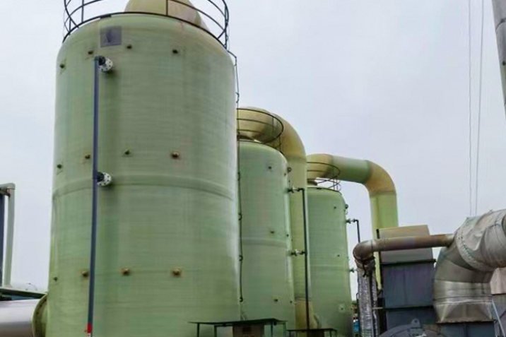
An FRP mixing tank is designed twice. The first design is the vessel — cylinder wall, knuckle, bottom, laminate schedule and the resin system that has to survive the chemistry. The second design is the agitator support, and it is the one that gets skipped. The result is predictable: a tank that passes its hydrostatic test in the shop, then develops radiating cracks around the mounting pad, loses a mechanical seal within a month, or starts a low-frequency shake at 80% of its rated speed that nobody can explain. This guide sets out the loads an agitator actually transfers into a composite shell, how the geometry ratios of the mixing system determine the shaft length and therefore the tank height, the three mounting arrangements used in FRP practice, the laminate and bolting details that make a pad survive, and the commissioning checks that catch the problems while the contractor is still on site.
1. Why the Agitator Mount Is the Weakest Link in an FRP Mixing Tank
FRP is excellent in membrane load and indifferent in bending. A cylindrical shell resists internal pressure and axial load efficiently because the fibres are oriented where the stress goes. Local bending around a small attachment is a different problem: the load enters through a stiff metal flange sitting on a flexible laminated shell, and the shell has to transfer that point load into the wall in a few centimetres. Steel tolerates that concentration by yielding a little and redistributing; a cured thermoset laminate does not yield — it develops transverse microcracks in the resin, and a cracked resin matrix in a corrosive service is an open path to the load-bearing fibres.
Three consequences follow, and they shape everything else in this article:
- Strain, not stress, governs the local design. FRP vessel codes work with allowable strains precisely because matrix cracking is the failure mode of interest. ASTM D3299 uses a 0.1% hoop strain limit for filament-wound tanks; ASME RTP-1 caps corrosion-barrier tensile strain around 0.10–0.13% under sustained load and 0.20% under intermittent load, with design factors of 10 for sustained and 5 for intermittent loads.
- The mount is a fatigue detail. An agitator applies a rotating bending moment at the mount, tens of millions of cycles over a typical service life. A connection that is merely strong enough for the static load will crack in fatigue if the strain range is not controlled.
- Misalignment multiplies the problem. Unlike a pump casing, the tank top is not a machined datum. If the mounting pad is not flat and square to the shaft axis, the gearbox foot is bolted down in a twisted condition and the mount carries a permanent preload before the first batch is even mixed.
This is why the agitator is chosen before the tank is drawn, not after. Retrofitting a mixer to an existing FRP storage tank is possible — ours are supplied with configurable top nozzles, support beams and mounting flanges — but the cheapest place to solve mechanical load is the design meeting.
2. Process Data the Agitator Vendor Needs Before the Tank Is Fabricated
Mixing geometry is a set of ratios, and every published mixing correlation assumes a reference geometry. Move away from the ratios and the power number, the blend time and the solids-suspension calculation all quietly become wrong. The standard reference configuration is a vertical cylinder with liquid depth equal to the tank diameter, four baffles at 90°, and one impeller of one third of the tank diameter set one third of the tank diameter above the bottom.
| Ratio | Reference value | Practical range and effect |
|---|---|---|
| Impeller diameter / tank diameter (D/T) | 0.33 | 0.30–0.50 for turbulent blending and solids suspension; 0.30–0.40 for radial gas-dispersion impellers; 0.15–0.25 for high-shear; 0.9–0.98 for close-clearance viscous duty. Large impellers give flow, small impellers give shear |
| Off-bottom clearance / tank diameter (C/T) | 0.33 | Lowering to about 0.25 improves solids suspension; raising above 0.5 splits the flow into two loops and leaves the bottom of the tank poorly served; below about 0.15 the impeller is starved |
| Liquid depth / tank diameter (Z/T) | 1.0 | Above roughly 1.2 the upper liquid falls outside the circulation loop and a second impeller is added, spaced about 1.0–1.5 impeller diameters apart — which lengthens the shaft and immediately raises the critical-speed question in section 4 |
| Baffle width / tank diameter | 1/10 to 1/12 | Four baffles at 90°, wall offset about one sixth of the baffle width (equivalently T/72 for a T/12 baffle), bottom clearance about one quarter of the baffle width |
| Solids suspension speed / just-suspended speed (Njs) | — | Operate about 10% above Njs; below it, solids accumulate on the floor no matter how long the batch runs |
The data package that goes to the agitator vendor or the tank vendor should therefore contain: fluid density and viscosity at both the lowest and highest operating temperature, solids content and particle size, gas rate if sparging, working volume and maximum liquid level, tank diameter and bottom shape, the required blend time or suspension criterion, and whether the vessel is open-top, closed with a manway, or pressurised. Two more items are frequently forgotten and both affect the mount: the maximum temperature the shell will see at the mounting pad, and whether the tank will be indoors or outdoors under wind load.
3. The Loads an Agitator Puts Into the FRP Shell
Five load types leave the drive and arrive at the laminate.
- Torque. Steady torsional load from the impeller. Torque per unit volume is the usual scale-up parameter, and the design torque follows from shaft power and speed: T = P / (2πN), or in imperial units T (in·lb) = 63025 × hp / rpm.
- Bending moment. The overhung shaft with its impeller acts as a cantilever. The lateral hydraulic force on the impeller, multiplied by the length from the drive bearing to the impeller, becomes a bending moment applied to the mount — usually the largest single load the pad sees.
- Axial thrust. Down-pumping impellers push down on the shaft and up into the drive, and the mount reacts it.
- Vibration and dynamic amplification. Unbalance, blade-pass forces and vortex shedding add alternating components on top of the steady loads, which is what makes the connection a fatigue detail.
- Thermal and differential-expansion load. A hot process at 80 °C grows a steel support frame considerably more than the FRP tank it is bolted to, so a rigidly tied assembly between a steel bridge and a composite shell can preload the mount.
A worked sizing example makes the magnitudes concrete. Take a 1.5 m diameter tank with a 0.5 m pitched-blade turbine (D/T = 0.33) running at 120 rpm in a fluid of 1,150 kg/m³, fully baffled. Impeller power P = Np · ρ · N³ · D⁵, with N in revolutions per second (2.0 s⁻¹) and a power number of about 1.7 for a baffled pitched-blade turbine: P = 1.7 × 1,150 × 2³ × 0.5⁵ = 489 W. The shaft torque is 489 / (2π × 2) = 39 N·m, or roughly 345 in·lb. Applying a service factor of 1.5 gives a nominal 0.75 kW drive, and a tip speed of 3.1 m/s — comfortably inside the 3–6 m/s band used for gas dispersion, and above the range where a small impeller turns too slowly to suspend anything. The point of the calculation for the tank builder is not the wattage; it is that the 39 N·m of torque and the corresponding bending moment at the pad are what the reinforcement has to be designed for, and both scale brutally with impeller diameter (to the fifth power in the power equation).
Practical rule: the pad and shell reinforcement should be designed for the agitator vendor's stated maximum bending moment and torque including a service factor — not for the values calculated at the normal operating point. Viscosity excursions, start-up with settled solids and power failure restart all push the transient load above the steady-state value, and start-up is when a marginal mount fails.
4. Critical Speed and Shaft Deflection: What Sets the Maximum Tank Height
A top-entry agitator shaft is an overhung cantilever, and its first lateral natural frequency is the critical speed. Run at the critical speed and the impeller's residual unbalance resonates with the shaft's own frequency; deflection grows without limit until the shaft whirls, the seal is destroyed and the mount is damaged.
Design practice therefore separates two regimes. A rigid shaft is operated below the first critical speed, conventionally at no more than 70% of it — 65% for heavy duty such as gas dispersion or uneven loads, and up to 80% for small laboratory units. A flexible shaft is operated above it: one refinery engineering standard requires flexible shafts to run above 1.25 times the first critical speed and below 0.7 times the second. Either way, a variable-frequency drive must have a block-out band around the critical speed — typically ±20% — programmed so the drive never parks or ramps slowly through resonance.
The physics that matters for the tank is the shape of the deflection curve. Static deflection of a cantilever rises with roughly the cube of length: double the shaft length and the same lateral force produces eight times the deflection. Impeller mass at the end of the shaft, impeller position, bearing span and the presence of a bottom steady bearing all move the critical speed as well, but length dominates. Practical implications:
- Two-impeller shafts on tall tanks (Z/T above 1.2) are a critical-speed problem before they are a mixing problem.
- Increasing shaft diameter is the most effective correction, because stiffness rises with the fourth power of diameter; a step from 60 mm to 75 mm transforms the margin.
- A bottom steady bearing converts the cantilever into a supported beam and raises the critical speed substantially, but it introduces product contamination from bearing wear, crevices that defeat clean-in-place, and alignment demands of its own.
- Symptoms of trouble are speed-specific: vibration that peaks at one speed, seal weeping that appears only at certain speeds, repeated bearing failures, or visible shaft whirl at the tank top. Vibration that is present at every speed is unbalance or misalignment, not resonance.
5. Mounting Arrangements: Nozzle-Mounted, Frame-Supported and Side-Entry
There are three practical arrangements for putting an agitator on an FRP vessel, and the choice is a structural decision about who carries the load.
| Arrangement | Load path | Best fit | Watch out for |
|---|---|---|---|
| Centred nozzle-mounted, drive bolted directly to a reinforced top nozzle or pad | All torque, bending and thrust into the shell top; drives through the pad laminate | Small to medium drives on closed tanks where a shaft seal is required; the most compact arrangement | |
| Off-centre nozzle mounting, typically 10–15° from vertical | As above, but with a deliberate side load on the shaft | Small vessels and duties where baffles are undesirable — the angled entry breaks the rotational symmetry and controls the vortex by itself | |
| Frame- or bridge-supported, independent of the vessel | Agitator loads go to the steel frame and the structure; the FRP top carries only seal alignment loads | Large drives and tall shafts on FRP tanks — long-standing practice in composites, because it isolates mechanical loads from a shell that is poor in local bending | |
| Side-entry, through a shell nozzle or wall boss | Bending and torque introduced into the shell wall below the liquid line | Large storage tanks where top entry is impossible; blending without baffles |
The side-entry case deserves its own caution. The propeller is normally set pointing slightly downward and off the tank centreline, and the tank must be full before start-up, because an unbaffled side-entry mixer started in a partly empty tank will whip the shaft and load the nozzle in ways the design never covered. The nozzle or wall boss also needs a local laminate build-up and, for anything but the smallest unit, an external steel bearing plate to spread the moment into the shell.
6. Reinforcing the Mount: Pad Geometry, Laminate and Strain Control
Whatever the arrangement, the mount detail is built the same way in principle: spread the load over enough laminate that the local strain stays inside the code allowables, and keep every load path continuous into the structural wall.
- Metal bearing plate or embedded pad. The bolted connection should bear on a steel plate — or on a laminate pad that was laid up with reinforcement oriented to the load — rather than on the shell surface. The plate turns a point load into a distributed pressure and gives the bolted joint a surface that will not crush.
- Tapered over-lamination. Secondary-bonded reinforcement around a nozzle or pad should be laid up with a tapered edge — a long, shallow transition, classically about 12:1 — so that the load is fed gradually into the parent laminate instead of terminating in a stress-raising step. Sharp-edged patches are where delamination starts.
- Continuous load path into the shell. Where the mount load is significant, the stiffening should continue down the shell — ribs, a thicker local laminate band or a top stiffener ring — so the moment is not carried by the top knuckle alone. ASME RTP-1 addresses shell attachment supports, opening reinforcement and secondary-bond shear as separate design items precisely because each is a different failure mode.
- Strain budget in the pad. The design should keep local strains within the corrosion-barrier limits quoted earlier (about 0.10–0.13% sustained, 0.20% intermittent, with design factors of 10 and 5). Where a hot or aggressive duty is involved, the pad must also retain the same corrosion barrier as the shell: a reinforcement laminated on top of the shell without restoring the resin-rich inner surface leaves an unprotected path in the wetted area.
- Access for the seal and the shaft coupling. The coupling and seal need to be reachable, and the drive needs to be removable without cutting the tank. Agitator-mounted pedestals that hold a mechanical seal must be supported so that seal alignment does not depend on the FRP top's flexibility.
7. Bolting, Gaskets and the Shaft Seal Interface
Bolting an agitator to a composite pad is not bolting to steel. Through-bolts with steel backing plates or cast-in inserts are preferred over self-tapping fasteners, edge distances have to respect the laminate rather than the bolt, and torque values come from the tank or pad manufacturer — over-torque crushes the laminate around the hole, under-torque lets the joint breathe under the rotating bending moment. The bolt-grade, edge-distance and bearing design logic is the same as for any FRP structural connection and is set out in our FRP structural bolted connections guide; the gasket and bolt-torque specifics for vessel nozzles are in the FRP tank nozzle and manway design guide.
The seal is where agitator and pump practice diverge, and specifying it wrongly guarantees failures. A pump shaft is held to a few thousandths of an inch of runout at the seal faces; a mixer shaft, because it is a long cantilever in a moving fluid, routinely runs 0.03–0.15 in (about 0.8–3.8 mm) of total indicated runout at the seal, and agitator seals are designed to tolerate at least about 3 mm. That is why API 682, written for centrifugal pumps, is the wrong specification for a mixing vessel: the appropriate references are agitator-specific, such as DIN 28138 and DIN 28154 in Europe or PIP RESM003. Practical consequences:
| Interface | What to get right |
|---|---|
| Shaft straightness | Shop-straighten after welding; runout beyond about 0.13 mm (0.005 in) accelerates seal and bearing wear |
| Seal type | Packing seals are unsuitable for explosive or highly toxic media; cartridge mechanical seals simplify installation; double seals with a barrier fluid are the norm for hazardous media and pressurised vessels |
| Seal support | Seal alignment depends on the pedestal, so a tank-supported seal needs a top structure stiff enough to hold alignment — otherwise use an independently supported seal with the drive on a separate beam and a flexible coupling |
| Thermal path | Mixer seals receive heat from the process up the shaft, which is the opposite of a pump seal's face-generated heat; cooling measures belong in the seal housing, not in the flush plan |
8. Baffles: Geometry, Hardware and FRP-Specific Detailing
Baffles convert swirling motion into top-to-bottom circulation. Without them the fluid rotates as a solid body, a central vortex forms, air is entrained and mixing collapses regardless of the power input. The standard arrangement is four flat baffles at 90° at the wall, each about one tenth to one twelfth of the tank diameter in width, with the wall offset around one sixth of the baffle width to keep material from stagnating behind the plate. Baffling also raises the impeller power number — a pitched-blade turbine moves from about 1.3 unbaffled to about 1.7 fully baffled — so baffle sizing and drive sizing are one calculation, not two.
Two exceptions are worth remembering. In high-viscosity duty, above roughly 10,000–20,000 cP, the fluid does not form a vortex and baffles add drag without benefit; partial or omitted baffling is then normal. And in small vessels an off-centre or angled agitator achieves the same flow asymmetry without touching the vessel wall.
On an FRP tank the baffle is a composite component, not a bolted metal strip, and three detailing rules follow. First, laminate the baffle to the shell in a continuous joint rather than bolting it through the wall, so no corrosion path is opened. Second, use the same or a compatible corrosion-resistant resin system as the tank interior, so the baffle's wetted surface is not the weakest chemistry in the vessel. Third, support tall baffles from the shell with brackets at intervals so they resist the fluid force as a beam rather than as a cantilever hanging from the top. Where the baffle must also act as a heat transfer surface, pipe coils doubling as baffles are a common solution, but they add both thermal and mechanical load at the wall and their support should be checked in the same calculation as the agitator mount.
9. Temperature, Chemical and Static-Electricity Limits of FRP Mixing Tanks
Mixing changes the duty the tank sees, so the material limits differ from the equivalent storage tank. Three limits matter most.
- Temperature. Resin choice sets the ceiling and the code sets a floor on thermal capability — ASME RTP-1 requires the laminate resin to have a heat deflection temperature of at least 82 °C (180 °F) to qualify. As a working guide, isophthalic polyester composites are used to about 60–70 °C continuously, vinyl ester grades to about 90–100 °C, and post-cured epoxy laminate considerably higher. Agitation adds mechanical energy to the fluid; in a hot tank that energy is heat, and the fluid temperature at the impeller discharge can be above the bulk reading.
- Chemistry, including the new chemistry you create. Mixing can generate conditions the tank was never bought for: neutralisation raises temperature and can create local concentration peaks, and settling solids can abrasively polish the corrosion barrier. Where aggressive acids or oxidants are involved, dual-laminate construction with a thermoplastic liner (PP, PVC or PVDF) is often the right answer; the liner selection logic is covered in our dual-laminate FRP equipment guide, and the resin comparison in FRP resin selection for chemical equipment.
- Static electricity. FRP is an electrical insulator, and mixing a flammable solvent in an insulated vessel is a charge-generation experiment. Recommended practice for static electricity in flammable atmospheres requires bonding and grounding of all conductive parts and control of charge generation; on an FRP tank this has to be designed in, through conductive liners or antistatic resin layers and a grounded metal ring on the pad and agitator. The relevant principles are the same as those behind our antistatic FRP pipe guide, and the agitator mount is the natural place to bring the ground path through the shell.
10. Commissioning and Acceptance: Runout, Vibration and the First 72 Hours
The last chance to catch a mount problem is commissioning, and it costs almost nothing compared with a cracked pad in service.
| Check | Method | Typical acceptance basis |
|---|---|---|
| Shaft runout and verticality | Dial gauge at the seal region and at the lower impeller, slow barring by hand | Runout within the mount/seal supplier's tolerance; straightness within about 0.13 mm on a shop-straightened shaft |
| Alignment of drive, coupling and seal | Feeler gauge or laser alignment on the coupling; check pad flatness before bolting down | Coupling misalignment within the coupling manufacturer's limit; no gap or preload induced at the pad feet |
| Bolt torque on the mounting pad | Torque wrench to the specified value in a cross pattern; re-check after first 24 hours of running | All fasteners at specified torque, no laminate cracking or whitening at the washers |
| Vibration after warm-up | Broadband RMS velocity at the gearbox/bearing housings; sweep the full speed range if a VFD is fitted | ISO 10816-3 / ISO 20816-3 severity zones. For a machine in the 15–300 kW group on a rigid support the A/B, B/C and C/D boundaries are 1.4, 2.8 and 4.5 mm/s RMS; large groups on rigid supports use 2.3, 4.5 and 7.1 mm/s. Agitator-specific specifications commonly limit bearing vibration to about 4.5, 7.1 or 11 mm/s RMS depending on drive power, and no resonance peak is acceptable anywhere inside the operating band |
| Visual inspection of the pad and shell after the first batches | Look for resin whitening, radiating cracks, weeping at the nozzle, fretting dust around the washer faces | No cracking or weeping; any whitening at the pad is a strain problem and must be investigated, not painted over |
Keep the sequence in mind when troubleshooting. Vibration that appears only at certain speeds and disappears elsewhere is a resonance or critical-speed issue — change the speed band or stiffen the shaft, do not keep tightening bolts. Vibration at every speed is unbalance or misalignment. Vibration that grows steadily over weeks with whitening at the pad is a strain and fatigue problem in the mount, and the fix belongs on the drawing: a wider bearing plate, a longer taper on the over-laminate, a thicker local laminate band, or an independent frame to take the loads off the shell altogether. Tank-side structural repairs use the same laminate and surface-preparation discipline described in our FRP tank repair guide and the field-lamination practice in FRP tank and vessel field erection.
Related reading: our filament-wound FRP chemical mixing tanks and vertical FRP storage tanks, the FRP tank nozzle and manway design guide, gel coat and corrosion barrier liner design, dual-laminate equipment selection and FRP structural bolted connections.
Need help selecting FRP products?
Our engineers answer technical questions free of charge.
Ask an Engineer on WhatsApp