
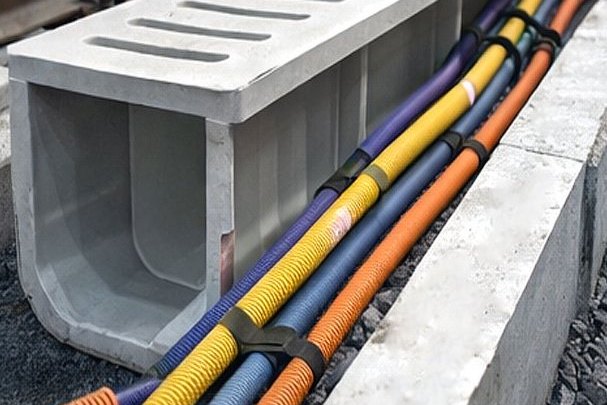
Trackside infrastructure is the least glamorous and most punishing duty in a rail project. A cable trough cover sits in ballast dust, takes the wash-down from every track machine, is walked on by maintenance staff, is expected to survive decades with no access, and — in any electrified system that uses the running rails as the traction return path — is part of an electrical environment that will quietly dissolve a chain of buried metallic structures if the wrong material is chosen. Composite profiles have moved into that space for reasons that are only partly about corrosion: they are electrically non-conductive, they are non-magnetic, and they are light enough for a two-person installation under possession.
That move brings three design questions that a supplier of "FRP profiles" is rarely asked and often cannot answer: what the stray-current regime requires of the structure, how the member behaves under hundreds of millions of load cycles, and how it is fixed into concrete that moves, flexes and gets wet. This guide works through all three, with the code values that decide them and the field details that decide whether the design survives contact with a track renewal programme.
1. What Wayside Infrastructure Actually Asks of a Material
The list of components that go into the trackside and station inventory is longer than most project teams realise when the material schedule is written, and they do not all sit in the same environment. Grouping them properly is the first step, because the governing requirement differs between groups.
- Cable route hardware — troughs and covers in the six-foot and at the cess, draw pits, route supports, brackets and clamps. The dominant loads are walk-on and machine loads plus ballast impact; the dominant degradation is UV at the surface, abrasion from ballast, and water standing in the section.
- Walkways, handrails and access platforms — station and depot walkways, platform-end access, maintenance stairs and the handrail systems that go with them.
- Electrically isolated structures — supports and enclosures that sit directly in the return-current path or adjacent to it, where conductivity is a design fault rather than a safety feature.
- Signalling and communications supports — signal structures, equipment housings and their mounting brackets, where non-magnetic and non-conductive behaviour protects the signalling circuit from induced interference.
- Component parts supplied onto rolling stock — a different regulatory world entirely, covered in section 9.
The reason FRP wins across the first four groups is not one property but a combination that no single metal offers: it does not corrode in the presence of chloride and track-machine runoff, it does not conduct, it does not carry eddy currents, and it does not need a protective coating that has to be maintained — which matters more than any material property, because trackside maintenance is expensive and rarely happens.
2. The Return Circuit Is the Design Driver Above Everything Else
In a DC traction system the running rails are the return conductor. Current leaves the substation through the conductor rail or overhead line, passes through the train, and returns through the rails to the rectifier negative bus. Because the rails are insulated from earth only by the track fastening system, the ballast and the formation, part of that return current leaks into the ground, travels through the soil and through buried metallic structures, and re-enters the rail somewhere closer to the substation. Where it leaves a metallic structure, that structure corrodes — anodic dissolution in its most efficient form, because the current does the work instead of a chemical gradient.
The European approach to this problem is contained in two documents that are written as a deliberately uneasy pair. EN 50122-1 deals with electrical safety and the return circuit, and its instinct is to bond accessible metalwork to the return circuit so that touch voltages stay low. EN 50122-2 deals with stray currents, and its instinct is the opposite: keep the return circuit floating with respect to earth, so that there is nowhere for the leakage current to go. The two documents resolve this with an explicit hierarchy — where they conflict, safety takes precedence — and the reconciliation device is the voltage limiting device (VLD), which holds a structure isolated from the return circuit under normal operation and closes the connection when the potential rises to a value that endangers a person. The 2022 edition of EN 50122-2 tightened the practical side of this by adding a laboratory test annex for track insulation materials and a separate annex on fastening systems.
For a material supplier this has one clear consequence: the specification of an FRP component in an electrified railway is not "FRP, UV stabilised, 1.5 m span". It is FRP of a stated volume resistivity, in a defined earthing class, with a defined position in the equipotential scheme, plus the fasteners that will not silently bridge the isolation that the whole installation exists to create.
3. The Numbers That Govern Stray Current
EN 50122-2 does not ask for a measurement of stray current, because stray current cannot be measured directly in service. It sets acceptance criteria on quantities that can be measured — track-to-earth conductance, rail potential shift and structure-to-earth potential — with the underlying benchmark being an empirical one: thirty years of experience indicates that the track itself suffers no stray-current damage if the average stray current per unit length does not exceed 2.5 mA per metre of single track line over a 25-year design life.
| Parameter | Open track formation (ballasted) | Closed track formation (slab, embedded) | Note |
|---|---|---|---|
| Track-to-earth conductance per length, G′RE | ≤ 0.5 S/km per track | ≤ 2.5 S/km per track | Per track; double the limit for a double-track line. Must hold for the whole life cycle, not just at handover. |
| Track potential shift, ΔURE | ≤ +5 V | ≤ +1 V | Off-potential subtracted. If either limit is exceeded, further investigation is required. |
| Average stray current per length | ≤ 2.5 mA/m per single track line | The empirical 25-year no-damage benchmark behind the conductance limits. | |
| Structure-to-earth average positive potential shift | ≤ +200 mV for reinforced concrete and metallic structures | Referenced to EN 50162; the criterion that protects tunnels, viaducts and adjacent buried utilities. | |
| Rail joint resistance | Increase ≤ 5 % of the initial resistance, except at insulated joints | Welded joints or low-resistance connectors; the return path has to stay a low-impedance path. | |
Criteria per EN 50122-2 for DC traction systems. The standard also requires insulated resin beds or rail boots on closed formation, adequate drainage to prevent water bridging the rail insulation, and – in the 2022 edition – laboratory qualification of the insulation materials and of the fastening systems themselves.
Read the table from the material side and two design rules fall out. The conductance limit is a statement about the entire track structure, so every component in that structure — including a cable trough support bolted to the slab and a cover resting on the cess — is either neutral to the calculation or part of the leakage path. A pultruded GRP trough with a volume resistivity above 1 × 10¹² Ω·cm is effectively neutral; a galvanised steel one is a conductive body sitting in the leakage field that then needs its own bonding and coating strategy. And the drainage requirement means that a trough which holds water is not just a maintenance nuisance, it is a stray-current risk, because standing water is the electrolyte that turns an isolated structure into a connected one.
4. Touch Voltage, Bonding and the Voltage Limiting Device
Safety is the document that takes precedence, and EN 50122-1 expresses it as a time-dependent limit rather than a single voltage. The human body tolerates a high potential for a very short time and a low one indefinitely, and the standard's limit curves follow that physiology: the permitted voltage rises steeply as the permitted exposure time falls.
| Exposure duration | Maximum body voltage, DC traction | Design consequence |
|---|---|---|
| > 300 s (steady state) | 120 V | Sets the trigger threshold for voltage limiting devices and the requirement for bonding of accessible metalwork in the contact line and collector zones |
| 300 s | 150 V | — |
| 1 s | 160 V | Drives the permissible fault clearance time at substations and the rating of the protection scheme |
| 0.2 s | 245 V | — |
| 0.1 s | 285 V | Typical high-speed protection clearance; beyond this the protection is too slow to rely on the curve |
| 0.02 s | 370 V | Short-circuit clearance only |
Values per EN 50122-1 for DC traction systems. AC systems carry a much lower long-term limit — 60 V — and maintenance areas in workshops are stricter still, at 25 V AC and 60 V DC long term, because people work there with tools for extended periods.
The practical consequence for a composite component is that it changes the earthing class of whatever it is attached to. In the contact line zone and the current collector zone, metallic parts must be bonded to the return circuit or protected by clearance or by an obstacle; a wholly or partly conductive structure has its own requirements; and in DC systems the standard's normative annex on voltage limiting devices covers the case where a structure is deliberately held open rather than bonded. A GRP trough, cover, bracket or handrail does not have to be bonded at all — which removes a bond that would otherwise have to be installed, inspected, tested and re-tested on a five-year cycle. That is the commercial argument for FRP on an electrified railway, and it is stronger than the corrosion argument.
The mistake to avoid is designing the composite component as an electrical insulator and then fastening it with a galvanised bracket to a bonded steel post at one end and leaving it floating at the other. The result is neither an insulated structure nor a bonded one, and it is a stray-current question that nobody can answer from the drawings. Decide the earthing class first, then specify the whole assembly to match it.
5. Cable Troughs and Route Hardware: The Largest Single Use
Cable route hardware is where the tonnage is, and it is also where the design detail is most often wrong. A trackside trough is a long, shallow, open section sitting in ballast, and the requirements on it are almost contradictory: it must keep cables dry and out of the ballast, it must drain so that it does not become a water bath, it must let heat out of a loaded power cable, and it must be strong enough that a person walking along the route, or a track machine's wheel, does not collapse it onto the cables.
The design variables that matter are few and each has a numeric answer:
- Wall thickness and section depth. Set by the walk-on and machine-load cases, not by stiffness alone. The load case should name a contact patch, not just a kilonewton figure.
- Drainage. The section needs a fall and defined drainage points. A GRP trough can be drilled or moulded with weepholes on site, which is an advantage over coated steel because the cut edges of a composite do not corrode — provided they are sealed against water ingress into the laminate, which is a factory or site resin operation and should be scheduled, not improvised.
- Thermal performance. Cable ratings in a trough depend on the trough's ability to dissipate heat. A closed cover resting on a fully loaded section traps air and derates the cable; the ventilation openings or the slotted cover that solves this has to be sized with the cable engineer, and the fire performance of a perforated cover is different from a solid one.
- Cover retention. Trackside covers are removed by wind, by wash-down and by track machinery. They need mechanical retention that does not rely on mass, and the retainer must be non-conductive and compatible with the earthing class decided in section 4.
- Access frequency. A cover that will be lifted once a decade can be heavier and simpler than one lifted monthly. The access interval belongs in the specification because it drives the mass per piece and therefore the installation method.
Combine that with the electrical requirement and the profile of a good trackside composite trough becomes clear: a pultruded U-section with a UV-stabilised gel-coat outer surface, a wall thickness sized to the walk-on case, moulded drainage and a defined fall, non-conductive retention clips, and a cover whose ventilation area has been agreed with the cable engineer. The FRP U-section cable trench and duct range is built in exactly that form factor, and it is worth reading the section drawings rather than the summary table, because in trough design the section geometry is the product.
6. Vibration and Fatigue: Designing for 107 Cycles
Wayside structures are not statically loaded. Every train that passes imposes a load cycle — through the ground, through the track and through the airborne pressure wave as much as through direct contact — and a busy line accumulates load cycles faster than any other structure in the built environment. A modest 200 train movements per day reaches 107 cycles in under 140 years, but the cycles that matter are not one per train: the dynamic content within a single pass, the pantograph and conductor gap effects, and the structural response of the member itself all contribute, and the design life of a trackside bracket is commonly evaluated at 107 or 108 cycles rather than at a static ultimate load.
Glass fibre composites behave very differently from steel under this kind of loading, and in the direction that matters they behave better. The relevant descriptor is the slope of the S-N curve expressed as σa = A · N−1/m: a higher exponent m means slower strength decay per decade of cycles. Structural steel in tension–tension fatigue slopes at about 3 to 5. A generic E-glass / polyester pultruded laminate slopes at about 8.0 to 8.3, and a qualification-grade unidirectional pultruded laminate has been measured at 8.51. Composites therefore degrade more slowly with cycle count than steel — the opposite of the common assumption that composites are the fragile choice in dynamic service.
| Design life | Cycles | Stress amplitude σa (P95 / 95 % survival) | Corresponding σmax at R = 0.1 | Note |
|---|---|---|---|---|
| Light duty / low traffic | 106 | 170 MPa | 377 MPa | Measured slope m = 8.51 on a structural UD pultrusion — an unusually flat curve for a glass laminate |
| Typical trackside accessory | 107 | 130 MPa | 288 MPa | The design life used in most certification programmes: 76 % of the 106-cycle amplitude |
| Long-life or high-frequency member | 108 | 99 MPa | 220 MPa | 58 % of the 106-cycle amplitude — into the endurance region |
Values from a published P95 / 95 % confidence tension–tension S-N curve for a qualification-grade pultruded unidirectional GFRP laminate. The 50 % survival fit is for material comparison only; certification input is the P95 line, with environmental and geometric partial factors applied on top. Laboratory coupons are dry, room-temperature and axial; real trackside stress is warm, wet, multi-axial and misaligned.
For a standard structural profile rather than a qualification-grade laminate the reference data points in a different direction, and it is worth reading carefully rather than borrowing a slope. Independent fatigue testing of full-size pultruded GFRP plates and of bonded lap joints made from the same plates, run to 107 cycles, recorded a loss of only 3 to 5 % of the single-cycle strength per decade of cycles — noticeably flatter than the 10 % per decade quoted in much of the earlier literature — and found a fatigue limit of approximately 25 % of the single-cycle failure load at 107 cycles, with the plates and the bonded joints converging on the same limit. A qualification-grade unidirectional laminate tested for wind-blade certification, by contrast, returns a steeper measured curve at m = 8.51, retaining about 76 % of its 106-cycle amplitude at 107 cycles. The two datasets are not in conflict; they are different laminates, specimen geometries and stress ratios. What they agree on is the design conclusion. Budget roughly a quarter of the single-cycle strength at 107 cycles, and where the member genuinely matters, buy a coupon curve for the actual laminate rather than borrowing one from another product family.
Applied to an EN 13706-3 grade E23 profile, whose minimum longitudinal tensile strength is 240 MPa, the quarter-of-strength rule puts the 107-cycle endurance stress at roughly 60 MPa. Two traps follow. First, a fatigue check is a stiffness check as much as a stress check, because the member's natural frequency and its dynamic amplification depend on modulus, and the stiffness loss that accompanies fibre failure in a composite can reach tens of percent before the member separates. Second, the fatigue-critical detail in an FRP assembly is usually the connection and not the member — bolted holes are stress concentrations, and the bonded-joint limit in the reference testing was no better than the plate limit. Design the connection with the same cycle count as the member.
7. Thermal Movement and the Joint at Every Fixed Point
Pultruded FRP is often described as having a high coefficient of thermal expansion. That is true in one direction and false in the other, and confusing the two produces either an over-designed joint or a buckled cover.
Along the fibres, the glass carries the load and the laminate's coefficient of thermal expansion is low — in the region of 7 to 10 × 10-6 per kelvin, which is below that of structural steel at about 12 × 10-6 per K. Across the fibres the resin dominates and the coefficient rises to roughly 20 to 30 × 10-6 per K. A long pultruded member therefore moves less than the steel member it replaces, and about two to three times as much in its transverse direction.
The practical calculation is the one that has always applied. A 6 m pultruded cover with a longitudinal coefficient of 9 × 10⁻⁶ per K and a service temperature swing of 45 K — a realistic range for a trackside component in a continental climate, from a cold night to a surface temperature well above air temperature in summer sun — moves 6 × 9 × 10-6 × 45 = about 2.4 mm. The equivalent steel cover moves about 3.2 mm. Neither figure justifies a complex expansion joint, but both mean that a cover bolted hard at both ends will either bow or pull its fixings, and a continuous run of trough strapped to a slab will accumulate the movement of every length in it.
The standard detailing answers are unremarkable and effective:
- Fix at one point per length and allow the rest of the run to slide, with restrained clips rather than tight bolts.
- Keep a nominal gap at every butt joint, and size it from the movement calculation rather than from a standard drawing detail.
- Never bridge a structural expansion joint with a continuous trough without a purpose-made sliding section.
- Remember the transverse coefficient: a wide cover restrained on both long edges at close centres will develop higher local stress than the longitudinal calculation suggests, because the dimension that is growing is the one that is constrained.
8. Fastening into Concrete and Steel
Almost every FRP wayside component is a bracket, a support or a cover retention detail, and almost all of them land on existing concrete or on a steel post. The fastening design therefore decides as much of the outcome as the composite does, and it is the part of the package most often left to site.
Post-installed anchors in concrete are designed to EN 1992-4, working from the European Technical Assessment of the specific product. Three of its rules catch composite assemblies in particular. The minimum edge distance and minimum member thickness are product-specific and are not negotiable on a narrow concrete kerb; the standard treats an anchor as "far from the edge", which allows the concrete edge break-out check under shear to be omitted, only when the edge distance reaches the greater of 10·hef and 60·dnom — a large distance, rarely achieved on a trackside kerb; and the design must also be checked for fire, where stainless steel and carbon steel behave quite differently.
| Parameter | M8 | M10 | M12 | M16 |
|---|---|---|---|---|
| Minimum edge distance cmin | 40 mm | 45 mm | 55 mm | 65 mm |
| Minimum member thickness hmin | max(1.5·hef; 80 mm) | max(1.5·hef; 100 mm) | max(1.5·hef; 120 mm) | max(1.5·hef; 120 mm) |
| Tensile resistance, A4-70 stainless, C20/25 | 9.5 kN | 12.6 kN | 18.4 kN | 27.9 kN |
| Shear resistance, A4-70 stainless | 8.3 kN | 12.8 kN | 19.2 kN | 35.3 kN |
| Shear resistance, A4-50 stainless | 3.8 kN | 6.3 kN | 8.8 kN | 16.4 kN |
| Characteristic tensile stress in fire, stainless A4, Ø12 and above, hef ≥ 50 mm | 30 N/mm² at 30 min · 25 N/mm² at 60 min · 20 N/mm² at 90 min · 16 N/mm² at 120 min (carbon steel: 20 / 15 / 13 / 10 N/mm²) | |||
Indicative values for a typical ETA-qualified mechanical anchor in cracked concrete C20/25, standard embedment, temperature range I, no edge or spacing influence. Fire values from EN 1992-4 Annex D. Product data must be taken from the current ETA for the anchor actually specified.
Four rules keep composite-to-concrete fixings out of trouble:
- Use A4 (316) stainless, not A2 and not galvanised. The shear capacity difference between A4-70 and A4-50 in the table above is a factor of more than two — the grade on the box is a design input, not a purchasing preference. In chloride-laden tunnel or coastal exposure, A4 or a higher-alloy stainless is the only sensible choice.
- Isolate dissimilar metals. A stainless anchor bearing directly on a galvanised bracket in a wet, chloride-bearing environment creates a galvanic couple in which the zinc is the anode. Isolating washers and sleeved holes solve it; ignoring it produces the failure mode in about two winters.
- Do not clamp composites to the point of crushing. Pultruded sections carry high axial stress and low through-thickness stress. Bolts bearing directly on a hollow section will crush it long before the bolt is at its design tension. Use spreader plates or washers sized to the section wall.
- Design for slotted or oversized holes. Deliberately oversized holes and a defined tightening torque keep the member from being clamped into a position that thermal movement or concrete settlement will fight. On a bridge deck, it will settle.
9. Fire: Which Standard Actually Applies
Rail fire specifications are the most frequently mis-cited documents in this field, and the error almost always costs a test programme. EN 45545 is a series about railway vehicles. It is the right framework for materials built onto rolling stock, and it is the wrong framework for a station platform edge, a tunnel walkway or a trackside cable trough, which fall under national building regulations, the infrastructure owner's own rules and, in Europe, the EN 13501-1 classification system. Projects that quote "EN 45545-2 HL3" for a fixed installation usually mean "low smoke, low toxicity, documented", and the document that can actually deliver that is a reaction-to-fire classification.
For components supplied onto vehicles — which includes a great deal of cable management hardware, conduit and interior fit-out — EN 45545-2 applies, and the assignment is by product type and location rather than by judgement. It defines 28 requirement sets in the current edition, up from 26 in the 2013 edition, and classifies each product against the hazard level HL1, HL2 or HL3 derived from the vehicle's operation and design category. Cable management components that are not individually listed are generally assessed against the requirement sets R22 (interior) and R23 (exterior).
| Requirement set | Product scope | Parameter | HL1 | HL2 | HL3 |
|---|---|---|---|---|---|
| R22 | Non-listed interior products with an exposed area ≤ 0.2 m²; interior supply line systems; chokes, coils, pipes and hoses | Limiting oxygen index, EN ISO 4589-2 (min) | 28 % | 28 % | 32 % |
| Smoke optical density Ds max, ISO 5659-2 at 25 kW/m² (max) | 600 | 300 | 150 | ||
| Toxicity index CIT, NF X 70-100 at 600 °C (max) | 1.2 | 0.9 | 0.75 | ||
| R23 | The exterior equivalents of the R22 scope | Limiting oxygen index (min) | 28 % | 28 % | 32 % |
| Smoke optical density Ds max (max) | — | 600 | 300 | ||
| Toxicity index CIT (max) | — | 1.8 | 1.5 | ||
| R24 | Printed circuit boards | Limiting oxygen index only (min) | 28 % | 28 % | 32 % |
Limits per EN 45545-2:2020 with Amendment A1:2023. R24 and R25 are LOI-based sets for printed circuit boards and are generally treated as a fallback where the fuller R22 or R23 programme cannot be met; R26 covers small electrotechnical products by vertical burn testing. A general-purpose polyester grating will not reach HL3 on any of these metrics — a phenolic system will.
Two points close the loop. First, HL3 is not something a supplier can volunteer: the hazard level comes from the route and the vehicle, and a certificate at HL1 is not a fallback for a project at HL3. Second, an ASTM E84 Class 1 rating, an EN 13501-1 B-s1,d0 class and an EN 45545-2 R22 pass are three different things measured three different ways; a project should state which one it is being held to, and the answer is usually determined by the client's approval authority rather than by the material.
10. Specification Checklist and the Mistakes That Recur
The whole of the above compresses into a requisition that a factory can quote against and an auditor can check.
- Earthing class. Bonded, voltage-limited, or intentionally isolated — stated once, applied to every component and every fixing in the assembly.
- Electrical properties. Volume resistivity with a test reference and a specimen conditioning statement, plus a CTI value where the component sits between live parts.
- Load cases. Walk-on with a defined contact patch, machine wheel load, ballast impact energy, and a stated deflection limit. Crack the load case open rather than quoting a single kN.
- Fatigue basis. The cycle count the member is designed for, and the stress limit taken either from a project coupon programme or from the 25 % of single-cycle strength rule.
- Thermal movement. Service temperature range, the joint gap that follows from it, and the fixing detail that allows the movement to happen.
- Fasteners. Grade by name (A4-70), isolating washers, spreader plates, tightening torque.
- Fire basis. Which document governs — EN 13501-1 for the fixed installation, EN 45545-2 with a named requirement set for anything going onto a vehicle.
- Surface and finish. UV-stabilised gel-coat for exposed runs; sealed cut edges on every drilled hole and every saw cut, because an unsealed edge wicks water into the laminate.
- Drainage and ventilation. Where the water leaves, and how the cable rating is maintained under a closed cover.
- Installation under possession. Piece mass low enough for two people, module length matched to the access window, and a spares quantity that assumes covers get lost.
The mistakes that come back most often are the opposite of exotic. Treating a station walkway as if EN 45545-2 applied to it, or a vehicle interior component as if the building code applied. Bonding one end of a component that was specified as an insulator. Substituting A2 stainless for A4 to save a few percent. Forgetting that a drilled hole in a pultruded section is an unsealed edge and a stress concentration at the same time. Designing the member for fatigue and the bolted connection for static strength. And specifying a longitudinal coefficient of thermal expansion for a component whose real constraint is across the fibres. Each of these is a line of text away from being fixed — which is the point of writing them down before the material schedule is issued.
Profiles, Troughs and Structures for Electrified Rail
We pultrude the structural profiles and the cable route sections that go into this kind of installation, in the resin systems the duty calls for. The pultruded FRP structural profile range covers the members behind walkways, platforms and equipment supports, the FRP U-section cable trench and duct range covers trackside cable routes, brackets and framing come from the pultruded FRP angle profile range, and the whole family sits under profiles and structural components.
For the surrounding engineering, see FRP grating in metro and tunnel projects under EN 45545-2, buckling of pultruded compression members, bolted connection design for FRP, pultruded pipe racks, bents and bracing, UV weathering and gel-coat systems and pultruded cable tray systems for corrosive environments. Send us the earthing class, the load case and the fire basis, and we will come back with the section, the jointing detail and the documentation that satisfies the approval authority.
Need help selecting FRP products?
Our engineers answer technical questions free of charge.
Ask an Engineer on WhatsApp