
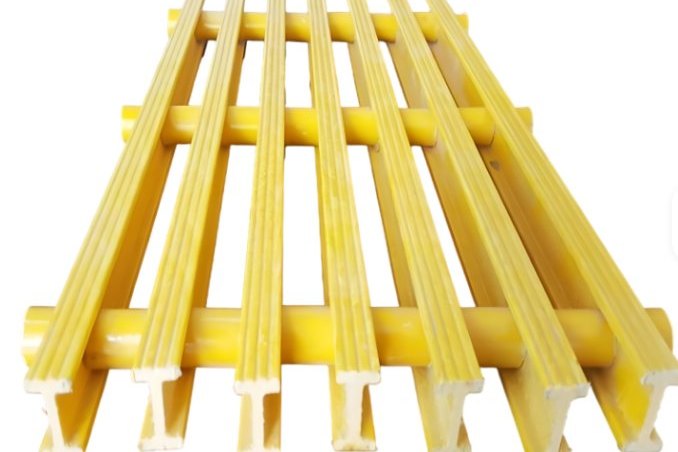
A steel pipe rack is usually drawn as a moment frame, with the columns fixed at the base and the beam-to-column connections designed to carry the transverse wind. Copy that drawing into pultruded FRP and it will fail its serviceability check by a factor of three or more, while passing every strength check comfortably. The reason is the modulus: at around 20 gigapascals, pultruded FRP is roughly a tenth as stiff as steel, and the sway of an unbraced frame varies inversely with the modulus. This guide shows what an unbraced FRP bent actually does, why the bracing that fixes it has to be designed tension-only, the load cases that really size the diagonal, what happens to an FRP rack in a fire, and the connection and movement details that a pipe rack needs and a walkway does not.
1. Why an FRP Pipe Rack Is a Bracing Problem
A pipe rack is a frame that carries a set of pipes at two or more elevations, and it is loaded in three directions. Gravity comes down through the beams into the columns. Wind and thermal movement act along the rack and across it. And the pipes themselves impose anchor and guide forces on the structure wherever the line is restrained. The rack's job is to carry all three without deflecting so far that pipes fall off their supports or that the stress in the pipes themselves becomes significant.
In FRP the third of those is the difficult one, because FRP structural sections are stiff enough to carry the gravity load and not stiff enough to resist lateral load in bending. That is not a defect of the material; it is a consequence of the stiffness-to-strength ratio, and the correct design response is not a bigger column. It is a bracing system.
- Gravity is carried in bending and compression, which FRP sections do well within their deflection limits.
- Lateral load carried in bending is the weak case, because the frame's sway depends on the column's flexural stiffness and the modulus is low.
- Lateral load carried in axial action is the strong case, because a diagonal works in tension or compression over its full cross-section instead of in bending over its depth.
- Frames are the right answer, bending is not. Every successful FRP pipe rack in service is braced or diaphragmed in some way.
2. The Bent: Members and Load Paths
A bent is one transverse frame: two or more columns, one or more beam levels, a base detail and a brace. The design decisions follow from the load path.
- Columns carry axial load from the pipes and bending from whatever lateral load the bracing does not take.
- Beams carry the pipe loads and, where they are used as part of the lateral system, distribute the horizontal load to the bracing.
- Bracing carries the horizontal load in axial action from the level at which it is applied down to the foundations.
- Base plates and anchors transfer axial load, shear and any moment into the foundation. FRP base plates need larger bearing areas than steel ones because the pin-bearing strength of the laminate is lower than steel's.
- Longitudinal bracing is needed as well as transverse. A rack that is braced only across each bent is a series of independent frames that can rack over in the other direction.
The single most useful decision in an FRP rack is where the bracing goes. Concentrating it in one bay at each end of a run, with the intermediate bents relying on the pipes and the longitudinal members to distribute the load, is the normal arrangement, and it means the bracing is designed once instead of being repeated on every bent.
3. Moment Frames Do Not Work in FRP
Take a bent with two 152 by 152 by 9.5 millimetre square tube columns, a clear height of 6 metres, a bay width of 4 metres, a horizontal design load of 6 kilonewtons at the top and an axial load of 15 kilonewtons per column from pipes, contents and insulation.
| Quantity | Value |
|---|---|
| Column area | 54.15 cm2 |
| Second moment of area | 18.41e-6 m4 |
| Radius of gyration | 58.3 mm |
| Modulus | 20.7 GPa |
With the bases fixed and the beam rigid, the sway at the top is V h cubed divided by twelve n E I, where n is the number of columns:
| Check | Result |
|---|---|
| Sway at the top | 141.7 mm |
| Limit h/150 | 40.0 mm, failed by a factor of 3.5 |
| Limit h/300 | 20.0 mm, failed by a factor of 7.1 |
| Column base moment | 9.00 kN.m per column |
| Bending stress | 37.2 MPa |
| Axial stress | 2.77 MPa |
| Combined stress | 39.9 MPa against a local buckling capacity of 165.6 MPa |
Read those two halves separately. On strength the frame is comfortable: it is using under a quarter of the member's capacity. On stiffness it is unusable: at 142 millimetres of sway, a pipe on a sliding support has moved far enough to be a concern, the frame looks visibly flimsy, and any pipe with a guide or a stop is being loaded in a way nobody designed for. The design is not close, and no reasonable increase in column size fixes it — halving the sway requires a column with twice the stiffness, which is a substantial and expensive section.
An FRP moment frame fails on stiffness while it passes on strength. This is the inverse of the steel design intuition, and it is why a rack that checks out on a stress basis can be unfit for service. Always check the sway first, because it will govern.
4. X-Bracing: Tension-Only Is the Design
Adding a braced bay changes the load path completely. With a diagonal from the base of one column to the top of the other, the horizontal load is carried as an axial force N = V divided by the cosine of the brace angle to the horizontal. For a 4 metre bay and a 6 metre height the diagonal is 7.211 metres long and its angle to the horizontal is 56.3 degrees, so the cosine is 0.5547 and the diagonal force for the 6 kilonewton load is 10.82 kilonewtons.
The sway then depends only on how much the tension diagonal stretches:
| Brace section | Area | Radius of gyration | Slenderness K L / r | Stress | Elongation | Sway | As a fraction of height |
|---|---|---|---|---|---|---|---|
| Flat bar 100 x 10 | 10.00 cm2 | 2.89 mm | 2,498 | 10.82 MPa | 3.77 mm | 6.79 mm | h/883 |
| Box 40 x 40 x 4 | 5.76 cm2 | 14.79 mm | 488 | 18.78 MPa | 6.54 mm | 11.79 mm | h/509 |
| Box 100 x 100 x 9.5 | 34.39 cm2 | 37.15 mm | 194 | 3.15 MPa | 1.10 mm | 1.98 mm | h/3,038 |
The flat bar is the most efficient of the three on a material basis and the least capable of acting as a strut. Its weak-axis buckling load over 7.211 metres is 33 newtons, against a diagonal demand of 10,817 newtons. The small box manages 495 newtons. Even the stocky 100 by 100 millimetre box, whose weak-axis buckling load of 18,647 newtons exceeds the demand, does not survive the load factors:
| Load case and time effect factor | Design capacity | Demand | Verdict |
|---|---|---|---|
| Wind or seismic, factor 1.00 | 13,053 N | 10,817 N | Just adequate |
| Live load, factor 0.80 | 10,442 N | 10,817 N | Short |
| Sustained storage, factor 0.60 | 7,832 N | 10,817 N | Short by a factor of 1.4 |
| Permanent load, factor 0.40 | 5,221 N | 10,817 N | Short by a factor of 2.1 |
Two conclusions follow, and they are the core of FRP rack design. First, the compression diagonal of an X-braced bay cannot be relied on in FRP at any practical slenderness, because a brace long enough to reach from the base of one column to the top of the next is far past any limit at which a pultruded section behaves as a strut. The X-bracing must therefore be detailed as tension-only, with the compression leg present but ignored. Second, the tension-only approach is not a compromise, because the flat bar that is useless in compression is the best of the three in tension: it produces the stiffest frame with the least material, at h/883.
The detailing that makes tension-only work is the same as in steel: a cross with a central intersection detail that allows the two diagonals to pass without connecting rigidly, and end connections sized for the tension force on the gross section through the bolt holes. What it does not permit is a single diagonal designed to work in both directions. A single diagonal relies on compression half the time, and in FRP it will simply bow out of plane.
5. The Load Cases That Actually Size the Bracing
Wind is rarely the governing case on an FRP rack, and the arithmetic shows why. Taking a design wind pressure of 900 newtons per square metre on the projected area of the two columns, 1.824 square metres, gives 1.64 kilonewtons — well below the 6 kilonewton figure used above, which represents the columns plus a transverse pipe run plus an allowance for other effects.
The case that usually governs is thermal. A pipe anchored to the rack imposes its thermal movement on the structure, and the anchor and guide forces can be large:
| Anchor load | Diagonal force at 56.3 degrees | Flat bar area required | Is a 100 x 10 flat adequate? |
|---|---|---|---|
| 10 kN | 18.03 kN | 2.68 cm2 | Yes, with margin |
| 25 kN | 45.07 kN | 6.70 cm2 | Yes, but only just |
| 40 kN | 72.11 kN | 10.72 cm2 | No; the flat bar is 10.00 cm2 |
The design consequence is that the rack's bracing has to be sized from the piping engineer's anchor and guide loads, not from the wind. A rack designed to wind alone and then asked to carry a 40 kilonewton anchor force is a rack that will be replaced. Three practical measures reduce the demand:
- Locate the anchors in the braced bay. An anchor force applied to an unbraced bent produces a framing action the bent was never designed for; the same force applied where the bracing is produces a direct axial path.
- Keep the guide loads low by design. Guide spacing, sliding surfaces and expansion loops are a piping decision that determines the structural decision.
- Allow the pipes to move independently. Where the rack cannot take the force, the pipe needs a support that permits movement rather than one that resists it, and the support has to be detailed so it cannot seize.
6. Fire Protection and the Glass Transition Temperature
An FRP structure's fire performance is a resin question with a structural answer. Below the glass transition temperature the material behaves as designed; as it approaches and passes Tg the modulus falls and the creep rate rises, and a member that was carrying load stops carrying it. The minimum permitted Tg for a designable pultrusion is 82 degrees Celsius, and the permitted service temperature is that value minus 22 kelvin, giving a ceiling of 60 degrees for a minimum-grade profile.
- Phenolic profiles give the best fire performance, with low flame spread and very low smoke, but they are more brittle and more expensive, and their chemical resistance is not as broad as vinyl ester's.
- Intumescent coatings can be applied to a standard polyester or vinyl ester profile to a stated fire rating, and they are the usual answer where the structure must remain FRP for corrosion reasons and also hold a rating.
- Passive barriers at cable transits are required regardless of the tray material. A rated wall with an unsealed penetration is not a rated wall.
- Consider the failure mode. An FRP rack that loses stiffness in a fire sheds its load onto the pipes rather than twisting and dropping them, which is a different consequence from a steel rack collapsing. That difference should be reflected in the fire strategy, not assumed to be an advantage.
7. Cable Routing and Electrical Considerations
FRP's electrical insulating property is a genuine advantage on a rack carrying power and instrumentation, and it changes several details.
- No bonding is required for the structure itself, but every cable tray still has to be bonded as an equipotential system, so the tray needs a continuous metallic bonding conductor regardless of its own material.
- Separation distances between power and instrumentation are the same as on a steel rack. An insulating structure does not reduce electromagnetic coupling between cables.
- Support spacing for FRP trays is closer than for steel. The usual limiting span quoted for an FRP cable tray is around two metres, set by deflection rather than strength, and the tray must not be used to brace the rack unless it has been designed for that.
- UV exposure matters on an outdoor rack. The exterior of every profile needs a UV-inhibited, pigmented finish, and a rack in a hot climate will lose surface appearance within a few years without it.
8. Connections, Clamps and Thermal Movement
Pultruded FRP does not yield and does not redistribute load, so a connection that is loose under-designed load will not straighten itself out. Four details decide whether the rack behaves as analysed:
- Bolt holes are the weak point. The pin-bearing strength of a pultruded laminate is far lower than its tensile strength, and a connection is usually governed by bearing or by net-section tension rather than by the bolt. Larger bearing plates, more bolts in a line and generous edge distances are the standard response.
- Do not use adhesive bonding as the primary connection on site. Bonded joints are excellent in a factory; on site, with dust, moisture and temperature outside the controlled range, they are a liability unless the process is properly specified and inspected.
- Provide for expansion. FRP moves two to three times as much as steel, so long rack runs need slotted holes or sliding connections at intervals and a defined fixed point. The fixed point is usually in the braced bay, which also aligns with the piping anchors.
- Support clamps must not crush the profile. A bolted clamp holding a hollow profile will collapse the wall before it develops the friction a steel design assumes. Use a full-face saddle or a clamp designed for the section.
9. Inspection
An FRP rack needs a shorter and more specific inspection than a steel one, because there is no coating to fail as an early warning. Look for:
- Movement at the base plates and at the brace connections, which indicates a loose or bearing-failed bolt rather than a material problem.
- Discolouration or a chalky surface on south and west faces, which indicates UV degradation of the surface layer.
- Chalking or crazing at the mid-height of columns, which can indicate sustained over-stress rather than environmental attack.
- White or cloudy patches around holes and cut edges, which indicate moisture ingress along the fibres.
- Creep deflection measured against a baseline taken at commissioning. A rack that has continued to sag over years is carrying more load, or a sustained load case, than it was designed for.
10. FAQ
Can an FRP rack be designed as a moment frame at all? Only for very low lateral loads or very short heights, and the sway check will still govern. It is almost always cheaper to add bracing than to make the columns stiff enough.
Is a single diagonal ever acceptable? Only if it is designed for compression as well as tension, which in FRP means a short brace and a stocky section. Over a full bay width and height, a single diagonal will buckle in compression and the frame will sway half the time.
How much does FRP save in weight? About 75 per cent against steel for the same function, which reduces foundation loads and allows a rack to be erected without a crane in many cases. On a retrofit inside an existing plant, the foundation saving is often the decisive argument.
What does the bracing do to the aesthetics of the rack? It makes the braced bays visually denser than the rest, which is why bracing is normally placed at the ends and at one intermediate position rather than on every bent.
Can FRP profiles be painted? They can, but the point of specifying FRP is usually to avoid painting. The correct finish is a pigmented, UV-inhibited surface from the pultrusion, and paint should be regarded as marking, not protection.
11. Designing an FRP Pipe Rack That Behaves
At Henan HuanGang we produce pultruded fibreglass structural profiles for construction and building in the wide-flange, square tube, channel, angle and flat bar sections a pipe rack needs, in isophthalic, vinyl ester and fire-retardant resin systems. The three questions we ask first about a rack enquiry are the clear height, the bay width and the anchor and guide loads from the piping, because those three decide the bracing and the bracing decides everything else. Send us the rack geometry and the piping loads and we will come back with the member sizes, the brace arrangement, the base detail and the deflection at the design load.
Related reading: pultruded FRP compression members and buckling, bolted connections in FRP structures, adhesive bonding of FRP structural joints, pultruded FRP profiles in structural applications, pultruded FRP trusses and space frames, custom pultruded profiles, FRP cable tray in corrosive environments, passive cable fire protection, FRP compared with wood and aluminium structures, UV weathering and colour stability and FRP sheet piles and retaining walls.
Need help selecting FRP products?
Our engineers answer technical questions free of charge.
Ask an Engineer on WhatsApp