
Most refractory castable failures are not material failures. The bag was right, the grade was right, and the anchors were right — and the lining still came down. The damage almost always happens in the first hundred hours, in the space between mixing water and the first hour of firing, when water that was mixed into the lining has to leave it as steam without exceeding the tensile strength of a now-brittle ceramic body. This guide covers the four variables that decide the outcome: how much water goes in, how the material is mixed and placed, how it is cured, and the exact heat-up curve it is given.
A cement-bonded castable typically arrives at the form containing 8–12% water by weight, split roughly into 6–8% free water sitting in the pores and 2–5% chemically bound water held in the calcium aluminate hydrates, depending on cement content and mix water demand. Every kilogram of that water becomes roughly 1.7 m3 of steam — a volume expansion of about 1,700 times. If the vapour cannot escape as fast as it is generated, the pressure rises until it exceeds the tensile strength of the lining, and the failure is not a crack but an explosion. That is the whole physics of dry-out, and everything below is a control on it.
1. Four Decisions, in Order of Damage
Installation variables do not contribute equally. Ranked by how much damage they do when they are wrong:
- Water addition. Excess mixing water permanently increases porosity and cuts strength. It cannot be reversed by longer curing or a slower heat-up.
- The heat-up curve. Too fast through the boiling range means explosive spalling; too fast through 550–600 °C means quartz-inversion cracking.
- Mixing energy and sequence. Under-mixed, under-sheared material does not develop its bond, and no amount of careful placing will fix it.
- Placing and vibration. Air pockets and segregation create local weak zones that become the origin of later spalls.
Rule of thumb used across the industry: the controlled drying time in hours should be at least twice the lining thickness in centimetres. A 300 mm castable lining therefore needs at least 60 hours of controlled heating and holding — not 60 hours of production time with the burners open.
2. Know the Material Family Before You Mix It
The drying difficulty of a lining is set by its cement content, and therefore by how much water the mix demands. Classify the material before the bags are opened, because the same 300 mm section behaves completely differently across these families.
| Family | Cement content | Mixing water | Drying behaviour | Typical use |
|---|---|---|---|---|
| Regular / conventional castable (RCC) | 15–25% | 10–14% | Most water to remove; longest dry-out; most forgiving placement | Low-duty linings, non-critical zones |
| Medium-cement castable (MCC) | 8–15% | 8–10% | Moderate water, moderate dry-out | Ducts, cyclones, general furnace walls |
| Low-cement castable (LCC) | 3–8% | 5–7% | Less water but a denser, finer pore structure; spalling risk rises | Kiln inlets, riser ducts, burner zones |
| Ultra-low / no-cement (ULCC, NCC) | 0–3% | 4–6% | Least water; needs careful placement and curing; highest strength | High-wear, high-temperature zones |
| Self-flowing (SC) | 3–8% | 6–8% | Dense, placed without vibration; must be dried slowly | Complex shapes, congested anchor arrays |
ASTM C401, the standard classification of alumina and alumina-silicate castable refractories, is the reference to quote in a purchase specification. It classifies dense castables by lime content introduced by the cement — ultra-low cement grades sit at 0.2–1.0% CaO, low cement at roughly 1.0–2.5% — and further divides conventional castables by modulus of rupture after drying into normal strength (at least 300 psi / 2.07 MPa) and high strength (at least 600 psi / 4.14 MPa), with a separate class for insulating castables based on dried bulk density and volume stability.
The test methods matter as much as the classification, because they are the acceptance evidence you will be handed: C862 for preparing cast specimens, C865 for firing them, C133 for cold crushing strength and modulus of rupture, C113 for permanent linear change, and C134 for bulk density. A datasheet that quotes strength without telling you whether the specimen was dried or fired is quoting half a number.
| Property | Conventional | Low cement (LCC) | Ultra-low cement (ULCC) |
|---|---|---|---|
| CaO content | above 2.5% | 1.0–2.5% | 0.2–1.0% |
| Mixing water demand | 8–12% | 4–6% | 3.5–5% |
| Bulk density after 110 °C drying | 2.1–2.3 g/cm³ | 2.5–2.7 g/cm³ | 2.7–2.9 g/cm³ |
| Apparent porosity after 110 °C | 18–25% | 12–16% | 10–14% |
| Cold crushing strength after 110 °C | 40–70 MPa | 80–120 MPa | 100–150 MPa |
| Cold crushing strength after ~1500 °C | 30–50 MPa | 60–100 MPa | 80–130 MPa |
| Installation difficulty | Low | Moderate | High |
3. Water Addition: Half a Percent Too Much Costs 15–20% of Strength
Water is the only ingredient measured on site, and it is the one that ruins linings. The relationship is steep and it is one-directional: for every 0.5% of water added above the manufacturer's specification, open porosity rises by roughly 1.5% and cold crushing strength plus abrasion resistance fall by around 15–20%. The excess water leaves behind an interconnected capillary network as it evaporates, and that network is exactly the path that later lets alkali vapour and slag into the matrix.
Discipline that actually works:
- Measure by weight, never by eye. Use a calibrated scale or flow meter. A bucket, a hose and "that looks about right" is the single most common cause of a failed lining.
- Use potable water. No sea water, no pond water, no process water. Chlorides, sulphates and organic matter all attack the chemical bond.
- Control water temperature, 15–25 °C. Below about 10 °C hydration is retarded and setting times stretch beyond the safe formwork window; above about 30 °C the mix can flash-set in the pan.
- Stop at the turning point. Low-cement and ultra-low-cement mixes look dry and crumbly, then suddenly liquefy. That is the design consistency. Do not add more water because the mix does not look like ordinary concrete — it is not ordinary concrete.
- Never re-temper. Adding water to a batch that has begun to stiffen in the hopper destroys the cement gel structure permanently. Discard the batch instead.
- Work within the placement window. Once mixed, low-cement and ultra-low-cement material should be placed and consolidated within 15–30 minutes.
4. Mixing: Equipment, Sequence and Time
A free-fall drum mixer cannot generate the shear needed to disperse sub-micron silica fume and reactive alumina, and hand mixing with a shovel cannot either. Both are excluded for LCC and ULCC grades. Use a forced-action pan mixer with planetary blades and, ideally, edge scrapers.
A three-stage sequence gives repeatable results:
| Stage | Action | Duration | What you are looking for |
|---|---|---|---|
| 1. Dry homogenisation | Charge the full dry batch and run the blades | 1.5–2.0 minutes | Even dispersion of fines, deflocculants and anti-spalling fiber; no colour banding |
| 2. First water | Add about 80% of the measured water with the blades running | about 2.0 minutes | Powdery and dry at first, then a damp crumbly mass |
| 3. Trim and shear | Add the remaining 20% incrementally to the design consistency | 1.5–2.0 minutes | Rheological liquefaction; ball-in-hand holds its shape with a slight sheen |
Total wet mixing should not exceed about six minutes: frictional heat from the paddles accelerates hydration and eats into the working time. Never mix more than the mixer's rated batch capacity — the result is incomplete mixing and a lining whose strength varies from one lift to the next.
5. Placing, Lifts and Vibration
Castables are thixotropic: stiff in the bucket, fluid the moment shear is applied, and immobile again when it stops. That property is what makes placement possible and what makes over-vibration destructive.
- Lift thickness 150–300 mm, placed continuously so that each lift is consolidated into the previous one while still plastic.
- Free-fall height under 1 m. Dropping the material further lets coarse aggregate ricochet off the forms and settle away from vertical walls, leaving aggregate nests and cement-rich pockets.
- Poker vibrators at 10,000–12,000 vibrations per minute, inserted vertically on a grid roughly 1.5 times the radius of action — typically every 200–300 mm.
- Penetrate the fresh lift and 50 mm into the lift below so the horizontal interface is welded into one monolithic body. Layered cold joints are where linings delaminate.
- Hold each insertion 5–15 seconds, withdraw slowly, and stop as soon as air bubbles cease and a glossy slurry sheen appears at the surface. Continuing past that point sinks the coarse aggregate and floats the fines.
- Self-flowing grades need no vibration at all. Pour and let them level; vibration on a self-flow mix causes segregation.
Anchors, expansion joints, forms and vibration equipment must all be installed and checked before mixing begins, because once a low-cement batch is in the pan there are only 15–30 minutes to place it. Caulk every formwork seam: water escaping through an open joint leaves honeycombed corners that no heat-up curve can rescue. Anchor tips should be capped or coated to allow thermal expansion without cracking the surrounding refractory; the anchor design itself is covered in our refractory anchor systems guide.
6. Curing: The 24–48 Hours Nobody Can Shorten
Curing is when the hydraulic bond develops. It happens at ambient temperature, in moisture, before any heat is applied.
- Do not disturb the castable for 12–24 hours at an ambient temperature of 20–30 °C.
- Keep the surface damp, not wet. Cover with damp hessian, wet cloth or plastic sheeting and maintain moisture for 24–48 hours. Conventional castables depend on this most; LCC and ULCC benefit from it but are less dependent.
- Strip forms after 12–24 hours, once the material has hardened — not earlier, and not by levering against a green edge.
- Shade and shelter. Direct sun and hot dry wind dry the surface faster than the interior, which produces surface crazing and a skin that spalls on first fire.
- Never apply heat to accelerate curing. The dry-out curve starts when curing is complete, not before.
7. The Dry-Out Curve: What Each Hold Is For
A dry-out schedule is not a ramp with arbitrary holds. Each plateau sits at a temperature where a specific physical event happens, and each one exists because the failure mode in that band is different.
| Temperature band | Event | Risk if the rate is exceeded | Typical hold |
|---|---|---|---|
| 100–120 °C | Free water boils and leaves as steam | Steam pressure exceeds lining tensile strength: explosive spalling | 1 hour per 25 mm of lining thickness, minimum 12–24 hours |
| 150–350 °C | Chemically bound water released from calcium aluminate hydrates | Cracking and delamination between layers | 8–12 hours, longer at 250 °C and 350 °C for thick linings |
| 350–600 °C | Remaining hydroxyl water; oxidation of organic fiber residues | Weak body, spalling at the transition to ceramic bonding | 4–6 hours at about 600 °C |
| 573 °C | Quartz inversion (α to β), a 0.45% volume change | Cracking in silica-containing refractories | Slow to about 15 °C/h through the 550–600 °C band |
| 700–900 °C | Ceramic bond formation | Structural weakness; the lining never reaches design strength | Intermediate hold before the final ramp |
| above 1000 °C | Sintering begins | Shrinkage stress cracks at joints and anchors | Controlled ramp to operating temperature with a soak |
Two rules turn that table into a workable schedule. First, the hold at 110–120 °C is not negotiable and is not shortened by better material — if there is visible steam, hold until the steam stops. Second, the hold time scales with thickness: the standard practice is one hour per 25 mm of lining thickness at each plateau, subject to the minimum for the material family. A 300 mm dense castable lining therefore takes about 12 hours at each plateau before minimums are considered.
8. Ramp Rates and Hold Times by Lining Type
The first heat-up of a new lining is slower than any subsequent one, because on the second and later firings the water is already gone. Use the first-fire column for commissioning and the subsequent column for restarts after a short shutdown.
| Lining type | Max ramp, first fire | Max ramp, subsequent | Minimum hold at 110 °C |
|---|---|---|---|
| Dense castable, cement bonded | 25 °C/h | 50 °C/h | 24 hours |
| Monolithic, vibration cast | 20 °C/h | 40 °C/h | 24 hours |
| Insulating castable | 15 °C/h | 30 °C/h | 24 hours |
| Rammed or gunned material | 20 °C/h | 40 °C/h | 24 hours |
| Plastic refractory | 15 °C/h | 30 °C/h | 24 hours |
| Fired refractory brick | 30 °C/h | 60 °C/h | 12 hours |
| Ceramic fiber lining | 50 °C/h | 100 °C/h | 4 hours |
Worked example — a 300 mm low-cement castable duct lining:
Ambient to 110 °C at 25 °C/h ≈ 4 hours, then hold 12 hours (1 h per 25 mm) extended to 24 hours because the section is thick and LCC is dense. 110 to 350 °C at 25 °C/h ≈ 10 hours, hold 6–8 hours. 350 to 600 °C at 25–35 °C/h, with a slow pass at 15 °C/h through 550–600 °C for the quartz inversion, hold 4 hours at 600 °C. 600 °C to operating temperature at 40–50 °C/h with a final soak of at least 6 hours. Total controlled time before production: roughly 100 hours, or four to five days.
Every one of those intervals may be extended. None may be shortened. Any castable can be heated more slowly than the published curve; no castable benefits from being heated faster.
9. Anti-Spalling Measures and What They Actually Buy
The vapour path is the other half of the problem. You can lengthen the curve, or you can make it easier for steam to leave.
- Polypropylene fiber in the mix. PP fibers melt at roughly 160–170 °C and vaporise at about 340 °C. Where they melt, they leave a network of capillaries that connects the interior to the surface and lets vapour escape instead of building pressure. Dosages in refractory castables run around 0.02–0.05% by weight (18 micron microfibers disperse at 600 million fibers per kilogram); polyethylene fibers melt lower, at about 128 °C, and are used as extra insurance. Fiber changes the schedule you can use below the melting point — it does not remove the need for a hold at 110 °C, because the fiber has not melted yet at that temperature.
- Weep holes through the hot face. Where the cold face is sealed — pressure vessels, heavily insulated shells, linings with a steel backing that cannot be vented — 3 mm diameter holes drilled through the hot-face castable on roughly a 300 mm grid give the moisture somewhere to go. They cost almost nothing and they routinely save an installation.
- Vent the shell. Open every damper, inspection door and vent port before the curve starts and keep forced draft running. Venting the steel shell, or providing deliberate openings, lets the cold face dry out as well.
- Instrument both faces. Thermocouples at the hot face and the cold face, plus mid-thickness where the section is thick. The hold is complete when the cold face has reached the hold temperature, not when the hot face has. Relying on the hot face alone is how linings get heated through with the core still wet.
- Control the geometry. Vapour has to travel further in a thick section. Where the process allows, keep monolithic sections as thin as practical and back them with insulating castable or insulating fire brick rather than thickening the working lining. Insulating layers hold more water, so they need their own drying plan — drying the insulation before the hot face is cast, or venting through it, is standard practice in thick-lined vessels.
10. Instrumentation, Interruption and What To Do If a Burner Dies
A dry-out is a controlled process, and the control is temperature, not time. Log the curve continuously with thermocouples at the locations above, and treat any deviation as an event to be documented and corrected, not smoothed over.
The most damaging thing that can happen during a dry-out is an interruption. If a burner fails and the temperature drops, two bad things occur at once: the temperature reverses, and the steam flow reverses with it, driving moisture back into hotter material with far more force than the outward flow. If the burners cannot be restarted, the priority is to keep the lining warm and cool it in a controlled way (no faster than about 50 °C/h), then restart the heat-up from the beginning of the original curve rather than picking up where it left off.
Two more field rules that come out of the same physics:
- Never let a flame impinge on green castable. Direct radiant or flame contact on an unfired surface causes localised hot spots and spalling while the rest of the lining is still wet. Modulate burners and use excess air, or bring in a temporary dry-out burner arrangement, to keep gas temperature uniform.
- Watch the steam. If steam is visible anywhere in the system, hold. The appearance of steam is direct evidence that water is still being removed, and the hold is not finished until it stops.
11. After Dry-Out: Acceptance Checks Before Production
The lining is not commissioned when the curve ends. It is commissioned when someone has looked at it and tested it.
- Visual inspection of the whole surface. Look for spalled patches, cracks running through the thickness, delamination at lift interfaces, exposed or bent anchors, and opened expansion joints.
- Tap testing on accessible surfaces. A hollow response indicates a disbond between lining layers or between the lining and the shell. Mark it, and repair before production rather than after the first campaign.
- Witness coupons. Specimens cast from the same batch per ASTM C862 and fired per C865 give you cold crushing strength to C133, permanent linear change to C113, and bulk density to C134. Compare against the datasheet values for the grade you purchased — this is the only way to prove that the material placed is the material specified.
- Check anchors and expansion joints. Anchor tips should not have cracked the surrounding material; joints should still be open with their compressible filler intact.
- File the record. The curve log with thermocouple data, hold times, interruptions and deviations becomes the baseline for every future heat-up, restart and inspection of that lining.
12. Expansion Joints and Backup Insulation: Where Linings Fail Quietly
Two details cause more long-term trouble than any mixing error, and neither gets much attention at the pour.
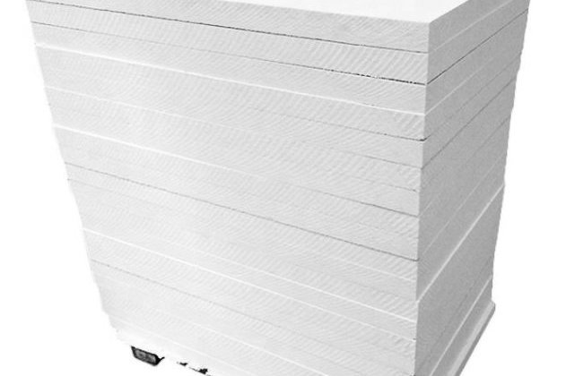
Expansion joints. A castable lining expands when it first fires, and if that movement has nowhere to go it produces compressive spalling or buckles the hot face. Joints are formed at intervals across the lining and around every penetration — burner openings, doors, tube penetrations and corners. Widths of a few millimetres are typical for castable work, filled with a compressible ceramic fiber board or blanket so the joint closes rather than filling with debris. Ceramic fiber board is the standard material because it compresses and still insulates; our aluminum silicate ceramic fiber board for furnaces is specified for exactly this role, and the wider family of seals is covered in our expansion joint seal guide.
Backup insulation. Behind the working lining, an insulating layer cuts shell temperature and heat loss. The combination used most often is insulating fire brick or insulating castable against the shell with ceramic fiber board between it and the dense hot face. Insulating fire brick is the low-water option — it arrives dry and needs no dry-out of its own, which is a genuine advantage in a thick section; see our mullite insulating fire bricks. Where insulation castable is used instead, remember that it contains more water than the dense hot face and is therefore the slowest part of the lining to dry.
13. Failure Gallery: Symptom, Mechanism, Prevention
| Symptom | Mechanism | Prevention |
|---|---|---|
| Violent spalling between 100 and 200 °C | Steam pressure exceeds the tensile strength of the lining before vapour can escape | Slower ramp, mandatory hold at 110 °C, anti-spalling fiber, weep holes, open vents |
| Large crack parallel to the hot face | Steep temperature gradient between hot and cold faces; differential expansion | Hold until the cold face reaches the hold temperature; instrument both faces; reduce ramp rate |
| Weak, friable body with high porosity and poor slag resistance | Excess mixing water (0.5% too much costs roughly 15–20% of strength) | Weigh the water; forced-action pan mixer; stop at the turning point; no re-tempering |
| Cracking specifically in the 550–600 °C band | Quartz inversion in silica-containing aggregate, a 0.45% volume change | Reduce to about 15 °C/h through that band; specify low-quartz grades where the section is thick |
| Section of lining falls away from the shell | Anchor oxidation or expansion cracking; or delamination at a cold lift joint | Correct alloy for the hot-face temperature; capped anchor tips; penetrate vibrators 50 mm into the previous lift |
| Cracks radiating from openings and corners | No expansion allowance at a penetration or corner | Form expansion joints around every penetration and at all corners; keep them free of debris |
| Surface crazing within hours of casting | Premature surface drying in sun or wind during curing | Cover and keep damp for 24–48 hours; cast under shade in hot climates |
Get the Lining Material and the Dry-Out Curve From One Source
HuanGang supplies high-alumina and fire clay refractory bricks, mullite insulating fire brick, and ceramic fiber board and blanket for furnace, kiln and duct linings — and, just as importantly, the data that lets your installation contractor build a heat-up curve that will not destroy the work. Send us the vessel geometry, the lining thickness, the working temperature and the shutdown window, and we will come back with the grade, the layer build-up and the dry-out constraints your contractor has to design within. Tell us what the lining has to survive and we will tell you how to install it.
Related reading: ceramic fiber board for furnace linings, mullite insulating fire bricks, fire clay bricks for ovens and kilns, high-alumina bricks for cement kilns, refractory anchor systems, refractory materials selection, ceramic fiber module installation, expansion joint seals, alumina brick grade selection by kiln zone and choosing between fiber blanket, board and module.
Need help selecting FRP products?
Our engineers answer technical questions free of charge.
Ask an Engineer on WhatsApp