
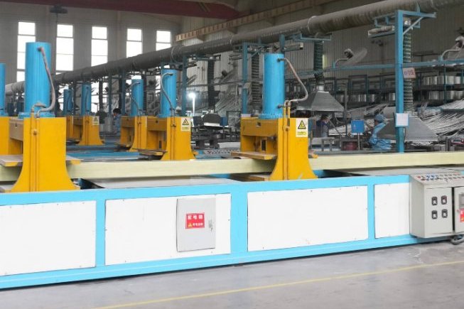
Every FRP factory has a waste problem it does not put on the website. A pultrusion line produces start-up slugs, die purge, off-spec profile, cut-off trim, dust from the finishing saw and packaging; a hand-lay or infusion shop produces resin drums, overspray, gel-coat waste, consumable peel ply and reject laminates. Because the cured material is a cross-linked thermoset, none of it can be melted and re-pelletised the way a thermoplastic scrap stream can. That single chemical fact is what makes composite waste a different commercial problem from plastics waste, and it is why the disposal route a factory chooses has real cost, compliance and customer-relationship consequences.
This guide is written from the position of an FRP manufacturer that has to make these choices with its own scrap, and from the position of a buyer who is increasingly asked by their own customers to document what happens at end of life. It sets out what is actually in FRP waste, the regulatory thresholds that decide which routes are lawful, what each recycling technology really recovers, how to cut waste at source on a pultrusion line, and the safety constraint — combustible dust — that most factories discover last.
1. Why Thermoset FRP Is the Hard Case
Thermoplastics recycle by re-melting. The polymer chains are not chemically bonded to each other, so heating softens the material and it can be re-formed. A cured polyester, vinylester, epoxy or phenolic matrix is the opposite: the resin has cross-linked into a three-dimensional network that cannot be softened or re-shaped without destroying it. The glass reinforcement is bonded to that network, and in a structural laminate the fibre-matrix interface is the whole point of the material.
The consequence is that recycling an FRP composite means separating two materials that were deliberately engineered to stay together. There are only four families of process that can do it:
- Mechanical size reduction — shredding and grinding the composite, then classifying the output. The fibres are shortened and the resin stays attached. Cheap, robust, and the only route that is genuinely commercial today at any scale for glass fibre.
- Thermal — pyrolysis (heating in the absence of oxygen) or fluidised-bed processing (hot air through a sand bed). The resin is decomposed to gas and oil, releasing the fibres.
- Chemical (solvolysis) — a solvent, sometimes with a catalyst, breaks the polymer bonds at lower temperature and can give higher-quality fibres.
- Co-processing in a cement kiln — the composite is fed as an alternative fuel and raw material, recovering the resin's energy and the glass's mineral content in one step. No discrete fibre is recovered, but no fibre needs to be recovered either.
Directive 2008/98/EC Article 4 sets the waste hierarchy that governs how these choices should be ranked — prevention, then preparing for reuse, then recycling, then other recovery including energy recovery, then disposal. The practical reading for an FRP factory is that the first question is not "which recycler do we use" but "how much of this stream can we stop generating", because nothing downstream is cheaper than waste that was never made.
2. What Is Actually in FRP Waste
Recycling economics start with a composition. A structural pultruded profile typically runs 60–70% reinforcement and filler by weight, with the remainder resin. Taking 65% glass and 35% resin as a representative mid-point, one tonne of cured pultrusion waste contains 650 kg of glass and mineral filler and 350 kg of cured resin.
That resin fraction is the reason the material cannot be landfilled in several European markets. Cured isophthalic and orthophthalic polyester resins are roughly 62% carbon by mass, so the total organic carbon content of the waste is:
| Glass + filler content | Resin content | Total organic carbon (TOC) of the waste | Multiple of a 3% TOC landfill limit |
|---|---|---|---|
| 60% | 40% | 24.8% | 8.3× |
| 65% | 35% | 21.7% | 7.2× |
| 70% | 30% | 18.6% | 6.2× |
The energy content follows from the same resin fraction. Cured polyester and vinylester resins have a lower heating value of roughly 25–30 MJ/kg; taking 27 MJ/kg gives 9.45 GJ of recoverable energy per tonne of FRP waste, equivalent to about 0.38 t of thermal coal or 0.20 t of natural gas on the same basis. That is a genuinely useful number for a cement kiln, and it is the commercial basis for co-processing.
The glass fraction is equally useful as a raw material. E-glass is an alumino-borosilicate, and its oxide content maps closely onto what a cement kiln already feeds:
| Oxide | Typical share of E-glass | Yield per tonne of FRP waste |
|---|---|---|
| SiO2 | 54% | 351 kg |
| CaO | 20% | 130 kg |
| Al2O3 | 14% | 91 kg |
| MgO | 3% | 19.5 kg |
| B2O3 | 7% | 45.5 kg |
| Na2O + K2O | 2% | 13 kg |
Silica, lime and alumina are the three principal components of Portland cement clinker, so 650 kg of the tonne substitutes directly for quarried raw meal. Boron and alkalis are the two components a kiln manager will want to talk about, because boron is volatile and alkali loading is a control parameter in cement chemistry — which is why co-processing approvals are issued against a defined feed rate and not as a blanket permission.
3. The Regulatory Position by Market
The compliance picture has moved faster than most FRP factories' documentation, and it differs sharply by country. The thresholds below are the ones that actually determine which route is available.
| Market | Instrument or rule | Practical effect on FRP waste |
|---|---|---|
| Germany | Ban on landfilling waste with TOC above 3%, in force since 2009 | Cured FRP at 18–25% TOC cannot be landfilled; co-processing or recycling required |
| Austria, Finland, Netherlands | National rules excluding composites from landfill | Same direction as Germany, with different exemptions |
| Netherlands | Landfill banned "in principle" under the National Waste Management Plan | Exemption possible where treatment cost exceeds a benchmark of about EUR 200 per tonne |
| France | Rotor mass reuse/recycle minima: 35% from Jul-2022, 45% from Jan-2023, 55% from Jan-2025 | A wind-sector rule, but it sets the procurement expectation for all large composite parts |
| EU wind sector | Industry self-imposed ban on blade landfill, effective 1 January 2026 | Sector acted ahead of legislation; capacity for composite processing is being booked forward |
| EU | Regulation (EU) 2025/40 (PPWR), in force 11 Feb 2025, applicable from 12 Aug 2026 | 70% recyclable by weight required from 2030 and 80% from 2038 for packaging placed on the EU market, with no general thermoset carve-out |
| EU | Directive 2008/98/EC Article 4 | Waste hierarchy governs route selection and must be documented |
| Global | ISO 14021:2016 | Sets the rules for any recycled-content claim, including the pre-consumer / post-consumer distinction |
Two of these deserve a comment. First, the German 3% TOC rule is the single most consequential regulation on this list, because it removes the cheapest option entirely for one of the largest composite markets in the world. Second, the PPWR route is aimed at packaging rather than at structural profiles, but it matters to any FRP producer who sells composite packaging, pultruded pallets, protective corner sections or composite components of packaging systems, because those do fall inside its scope and the 2030 threshold is not far away.
One caution on published cost figures. Widely quoted numbers for composite recycling — roughly $900–1,800 per tonne for mechanical recycling and pyrolysis against $60–150 per tonne for landfill — come from wind turbine blade decommissioning. Those costs are dominated by cutting and transporting 40–80 m blades. Clean, dry, already-sized pultrusion trim and off-spec profile arriving at a processor as 1 m offcuts does not carry that cost structure, and quoting the blade numbers for factory scrap will make every recycling option look uneconomic when it may not be. Measure your own logistics before you conclude anything.
4. Mechanical Grinding: What It Recovers and What It Costs You
Mechanical recycling is the workhorse. Material is shredded, then ground in a hammer mill or similar unit and classified into fractions. The output is not fibre in any usable textile sense — it is a graded mixture of resin-coated fibre fragments and resin-rich powder.
Independent analysis of ground GFRP recyclate has produced consistent findings on what the grinding does to the reinforcement:
- Single-fibre tensile strength reduced by 20–30%;
- Fibre modulus essentially comparable to virgin fibre;
- Fibre-matrix bond strength, measured by pull-out, reduced by about 50%.
The last of those three is the one that matters. Losing a quarter of the fibre strength is tolerable in many applications; losing half the interfacial bond strength means the recyclate cannot simply be substituted for virgin reinforcement at equal loading, because the composite's performance depends on load transfer at that interface, not just on fibre strength. This is why mechanically recycled GFRP is best understood as a filler rather than as a reinforcement — and why the applications that work are those where the recyclate replaces calcium carbonate or talc rather than glass fibre.
There is also a cost benchmark to be honest about: producing finely ground recyclate at a cost comparable to calcium carbonate is difficult, because energy for grinding does not fall as particle size falls. The factories that have made mechanical recycling work commercially have tended to attack the problem from one of two directions — improving the energy efficiency of the grinding circuit, or deliberately retaining fibre length at a coarser grade so the product sells into a higher-value application.
5. Reusing Ground Recyclate in Your Own Production
The most controllable route for a manufacturer is to put its own recyclate back into its own product, avoiding transport, gate fees and the market risk of selling an unfamiliar secondary material. The historical precedent is sheet moulding compound: one early German automotive composite recycler shredded and ground graded production and post-use waste into powder and fed it into new SMC at proportions up to 20%.
The penalty is real and must be budgeted. Published results for composites containing recyclate report flexural strength reductions of 10% to 54% across recyclate contents of 5% to 70% by weight. Interpolating linearly between the two published endpoints gives the following indicative schedule:
| Recyclate content by weight | Indicative flexural strength loss | Relative flexural strength |
|---|---|---|
| 5% | 10.0% | 0.900 |
| 10% | 13.4% | 0.866 |
| 15% | 16.8% | 0.832 |
| 20% | 20.2% | 0.798 |
| 30% | 26.9% | 0.731 |
| 50% | 40.5% | 0.595 |
| 70% | 54.0% | 0.460 |
Two warnings about that table, and they matter more than the numbers. First, it is a linear interpolation between two published data points and must not be used as a design allowable — the real relationship depends on recyclate particle size distribution, resin system, and whether the recyclate is fed as filler or as a partial reinforcement. Second, the reductions quoted are for flexural strength specifically; other properties move differently, and impact properties are typically the most sensitive.
The practical way to use recyclate internally without a design argument is to target the applications where the specification is not structural. Non-critical mouldings, tooling bases, backing layers, ballast and counterweight fill, pultrusion core fill, and packaging components are all candidates. Where recyclate is fed into a load-bearing pultrusion, the safe approach is to treat it as a mineral filler substitution at a fixed, controlled level and to re-certify the profile against the relevant grade — for structural profiles that means EN 13706-3, and for rebar it means the tensile and bond requirements behind our GFRP rebar pultrusion and QC checklist.
6. Pyrolysis and Fluidised Bed: Fibre Recovery and Its Penalty
Thermal processing decomposes the resin and releases the fibre. For carbon fibre this is a genuinely high-value business: carbon fibre recovered by pyrolysis retains 90% or more of its original mechanical properties, and commercial plants have operated at thousands of tonnes per year. For glass fibre the economics are much less attractive, and the reason is straightforward — recycled glass fibre cannot compete with virgin E-glass on price, so there is no margin to pay for the process.
The property penalty for glass is severe. Glass fibre recovered by pyrolysis loses strength progressively as the process temperature rises from 650 °C towards 800 °C. In fluidised-bed processing, where shredded composite at roughly 25 mm is fed into a sand bed fluidised with hot air, the polymer breaks down and vaporises and the fibres are carried out in the gas stream; at 450 °C glass fibre loses about 50% of its tensile strength while retaining its stiffness, which is enough to remove a polyester matrix. Higher temperatures remove more resin but cost more strength. Carbon fibre in the same process loses about 20% of its strength at 550 °C, again with stiffness retained.
Alongside the fibre, pyrolysis produces gas and oil that can be burned. One life-cycle assessment attributed a net energy retrieval of about 19 MJ per kg of composite processed by pyrolysis — after a process energy input of 2.8 MJ/kg, with outputs credited as LPG at roughly 2 MJ/kg, heating fuel oil at 9.2 MJ/kg and composite fillers at 10.6 MJ/kg. On that accounting pyrolysis recovers about twice the energy that cement-kiln co-processing recovers from the same material. The figure includes credits for retained filler material, so it should be read as an upper-bound comparison rather than as a kiln-equivalent fuel value.
| Route | Temperature or mechanism | What is recovered | Fibre condition after processing |
|---|---|---|---|
| Mechanical grinding | Ambient, hammer mill plus classification | Graded recyclate, resin-rich powder | Fibre strength −20 to 30%; modulus comparable; pull-out bond −50% |
| Pyrolysis | 400–700 °C, no oxygen | Fibre, pyrolysis oil, gas, char | Glass strength falls as temperature rises from 650 to 800 °C; carbon retains 90%+ |
| Fluidised bed | 450–550 °C, sand bed, hot air | Fibre and filler, fully oxidised resin heat | Glass about −50% strength, stiffness retained at 450 °C; carbon about −20% at 550 °C |
| High-voltage fragmentation | Repeated pulses up to 200 kV in water | Longer, cleaner fibre fragments | Better fibre length than mechanical; higher energy input |
| Solvolysis | Low temperature and pressure below 200 °C with reactive solvents, or sub/supercritical | High-quality fibre, potentially monomers | Best fibre quality of the thermal and chemical routes; still at laboratory and demonstration scale for GFRP |
| Cement co-processing | Kiln, roughly 1,450 °C | Energy plus mineral raw meal | No discrete fibre recovered, and none required |
Two operational realities sit behind that table. Pyrolysis carries a real risk of uncontrolled char on the recovered fibre and of carbon monoxide formation, so the off-gas has to be captured and treated and the fibre usually needs a post-treatment to remove residue. Fluidised-bed processing generates a substantial liquid waste stream that has to be handled, which is one of the reasons the process has not scaled as fast as its technical merits suggest.
7. Cement Kiln Co-Processing: The Only At-Scale Route Today
For mixed, contaminated or resin-rich GFRP with no clean fibre market to serve, cement kiln co-processing is currently the highest-volume route in Europe and the one most likely to be available to a factory exporting from China or selling into the EU. The mechanism is elegantly simple: roughly two thirds of the mass — the glass and mineral content — is incorporated into the raw meal and becomes clinker, while the remaining third, the organic resin, burns and displaces coal or gas. Published industry estimates put the CO2 benefit of that fuel substitution in the region of 16% for the displaced fuel.
Two constraints govern how much a given kiln will accept. The first is the feed specification: particle size, moisture and any non-composite contamination such as metal inserts, rubber gaskets or PVC foam core. The second is chemistry — alkali and boron loading in the kiln, and in some jurisdictions a limit on the total alternative fuel substitution rate.
There is also a hard boundary that catches people out: cement co-processing is suitable for glass-fibre composites but not for carbon-fibre composites. Carbon fibre is not a useful kiln raw material, and the material value of recycled carbon fibre is high enough that burning it is a straightforward waste of a valuable stream. A factory with both GFRP and CFRP waste must segregate them at source; a mixed bin has effectively destroyed the CFRP value.
An important framing point for a buyer: co-processing recovers material and energy but produces no recycled content in the ISO 14021 sense, because nothing returns into a new product. It is recovery, not recycling, in the language of the waste hierarchy. If your customer's requirement is a recycled-content figure, co-processing will not deliver one, and you need mechanical or thermal processing plus a genuine re-use loop.
8. High-Voltage Fragmentation and Solvolysis: Where They Stand
High-voltage fragmentation immerses composite in water between two electrodes and discharges repeated pulses of up to 200 kV, generating shockwaves that break the material apart. It is adapted from rock-mining practice and has been demonstrated on both GFRP and CFRP at laboratory and pilot scale. Compared with mechanical grinding it produces longer and cleaner fibres, which is exactly what you need if the recyclate is to function as reinforcement; the trade is a higher energy input per tonne.
Solvolysis uses a chemical solvent, sometimes with a catalyst, to break the polymer bonds. Low-temperature and low-pressure variants operate below about 200 °C at atmospheric pressure with reactive solvents; high-temperature and high-pressure variants use subcritical or supercritical conditions. Fibre quality from the low-temperature route can be the best of any process, and the high-temperature route is generally regarded as the less environmentally demanding of the two, but for GFRP the technique remains at laboratory and pre-industrial scale. The solvent has to be recovered or safely disposed of, which is the practical limit on scale-up.
The honest summary for a factory in 2026 is that mechanical grinding and cement co-processing are available now, pyrolysis is available for carbon fibre and marginal for glass, and the chemical routes are promising but not yet something you can build a waste contract around. Plan on the routes that exist and design for the routes that are coming.
9. Cutting Waste at Source: The Streams on a Pultrusion Line
Waste prevention is the one part of the hierarchy with an immediate payback, because every kilogram not generated is a kilogram you do not have to shred, classify, document, transport or pay a gate fee on. On a pultrusion line the streams are predictable, and each has its own best destination.
| Stream | Where it arises | Prevention lever | Best destination |
|---|---|---|---|
| Start-up and run-out slugs | Every die start and stop | Longer run lengths; campaign scheduling by profile and colour | Grind on site; reuse as filler |
| Die purge and pre-gel | Die entry, particularly after a break | Injection-die tooling instead of open resin bath reduces volatile loss and wet-out waste | Grind; keep separate from clean trim |
| Off-spec profile | Dimensional or surface failure | In-line dimensional and Barcol monitoring to catch drift early | Re-cut for shorter items; otherwise grind |
| Cut-off trim and end waste | Saw station | Tighter cut-length nesting; standard lengths that customers accept | Grind; cleanest stream in the plant |
| Finishing dust and swarf | Sanding, routing, drilling | Correct tooling and speeds; extract at the source | Captured by LEV; do not blend into re-usable recyclate |
| Resin and gel-coat residues | Bath dregs, drum heels, spray overspray | Catalyst and viscosity control; drum drainage; closed moulding where the part allows | Hazardous or special waste route, not composite recycling |
| Solvent and cleaning waste | Gun and bath cleaning | Solvent recovery unit; water-based release systems where feasible | Solvent recovery, then licensed disposal |
| Consumables | Peel ply, vacuum bag, breather, gloves | Reusable silicone bags where geometry permits | Segregated; often energy recovery |
| Packaging | Incoming resin and glass, outgoing finished profile | Returnable stillages and interleaves | Recycling; subject to PPWR recycled-content rules |
Two levers on that list consistently give the largest reduction for the least capital. Campaign scheduling — running the same profile and colour for longer, rather than changing over frequently — attacks the start-up slug stream, which is often the single largest contributor by mass. Closed tooling, whether an injection die on a pultrusion line or vacuum infusion instead of hand lay-up, attacks both the resin waste and the styrene emission problem in one move, and our guide to FRP manufacturing processes sets out the process-by-process waste and emission profiles.
10. Segregation, Particle Size and the Grinding Line
The single highest-value action in a factory recycling programme is not choosing a technology, it is keeping streams apart. Recyclate value collapses the moment streams are mixed in ways that cannot be undone.
Four separation rules do most of the work:
- By fibre type. GFRP and CFRP must never share a bin. The reason is not contamination in the abstract; it is that CFRP has a viable recycling market and burning or grinding it destroys that value.
- By resin system. Polyester, vinylester, epoxy, phenolic and thermoplastic matrix waste should be labelled separately. Downstream process temperatures and outcomes depend on the matrix.
- By contamination. Metal inserts, rubber seals, PVC or PET foam core, wood, and painted or coated surfaces all change the chemistry of the output. Where de-insertion is possible at the point of rejection, do it there rather than at the grinder.
- By cleanliness. Store composite scrap dry and covered. Wet or dirty feedstock grinds badly, classifies badly and produces a lower-grade product.
On the grinding line itself, the sequence that works is shred, then grind, then classify by sieve into a small number of named grades. A practical three-fraction split is coarse (roughly 2–10 mm, retaining fibre length and usable where some reinforcement value is wanted), mid (roughly 0.5–2 mm, the general filler grade) and fines (below 0.5 mm, resin-rich powder). The fractions should be bagged and labelled by grade, fibre type, matrix type and date — because the moment you cannot state the composition of a bag of recyclate, no customer with a specification can accept it.
If the material is destined for a cement kiln rather than internal re-use, the classification step can be much simpler and particle size is specified by the kiln rather than by you. That is one reason co-processing is the easiest route to start with: it needs segregation but not grading.
11. Combustible Dust: The Safety Constraint Nobody Plans For
Any process that grinds, saws or sands cured FRP generates a combustible dust, and this is the part of a recycling project that most often stops it. The glass fibre itself is not the fuel; the cured resin is. It is a genuinely deflagrable material, and the published safety data sheets for pultruded FRP profiles confirm it in the manufacturers' own words: one states that machining dust is combustible and classifies it as an St 1 dust with a KSt below 100 bar·m/s, and another states that grinding, drilling, sanding or cutting may generate dusts that could form explosive dust-air mixtures and classifies the dust at a KSt of 177 bar·m/s.
Those two published values span nearly a factor of two in deflagration severity, and that matters commercially because vent area scales with KSt. Using the NFPA 68 dust correlation for a 10 m3 enclosure at Pred 0.5 bar-g and Pstat 0.10 bar-g:
| Assumed KSt (bar·m/s) | Dust class | Required vent area | Relative to the KSt = 100 case |
|---|---|---|---|
| 100 | St 1 | 0.454 m2 | 1.00× |
| 150 | St 1 | 0.672 m2 | 1.48× |
| 177 | St 1 (upper) | 0.789 m2 | 1.74× |
| 250 | St 2 | 1.103 m2 | 2.43× |
A factory that guesses its dust severity low and installs the corresponding venting has bought a safety system sized for a different material. The correct approach is to have the dust tested — ASTM E1226 for KSt, Pmax and dP/dt, ASTM E1491 for minimum ignition temperature, ASTM E2019 for minimum ignition energy, with the EN 14034 series as the European equivalent — and to have a Dust Hazard Analysis carried out under NFPA 660, the consolidated combustible dust standard that replaced the former separate documents. Testing the actual dust from the actual process is the only way to close this question.
The engineering controls around the grinder and the finishing station are then conventional, but they have to be actually installed:
- Local exhaust ventilation at the point of generation, not a general shop extract;
- Housekeeping on a defined interval with a target for maximum dust layer thickness, and never compressed air for blowdown — it creates exactly the suspended cloud you are trying to avoid;
- Bonding and grounding of ducting, hoppers and conveying equipment;
- Explosion protection on the dust collector, sized to the tested KSt;
- No ignition sources: control hot work, and use appropriately rated electrical equipment in the classified zone.
On the occupational hygiene side the applicable limits are worth writing on the wall. OSHA's permissible exposure limit for particulates not otherwise regulated is 15 mg/m3 total dust and 5 mg/m3 respirable; ACGIH's threshold limit values are 10 mg/m3 inhalable and 3 mg/m3 respirable, which are lower and represent current best practice. For fibrous glass specifically, NIOSH recommends 3 fibres/cm3 and ACGIH sets a TLV of 1 fibre/cm3 for respirable glass fibre. Our article on FRP machining: drill speeds, blade selection and edge sealing covers the tooling choices that reduce dust generation at source, which is cheaper than extracting it afterwards.
12. Documentation Buyers Now Ask For
Compliance is increasingly a paperwork problem rather than a technical one, and an FRP supplier who cannot produce the paperwork loses the order regardless of the material quality. Five documents cover most requests.
| Document | What it must state | Common failure |
|---|---|---|
| Waste transfer or disposal record | Stream description, quantity, destination facility, permit reference, date | Aggregating all composite waste into one line with no route detail |
| Recycled content declaration | Percentage by weight, boundary (whole product or component), and pre-consumer versus post-consumer split per ISO 14021 | Claiming post-consumer content from in-house production scrap, which is pre-consumer by definition |
| Environmental Product Declaration | Life-cycle modules structured to EN 15804, including end-of-life and the module D credits for recovery | Omitting module D and therefore understating the benefit of a recycling route |
| Dust and process safety records | Dust testing results, Dust Hazard Analysis reference, vent sizing calculation, housekeeping regime | No test data at all, or data from a different process |
| Material traceability | Resin, glass and core batch references linked to the finished part or profile serial | Batch records held for the resin but not for the recyclate feed |
The single most common error here is the pre-consumer and post-consumer distinction. Under ISO 14021, pre-consumer material is manufacturing waste diverted from the waste stream and reintroduced into production, but it explicitly excludes material reworked within the same process that generated it. Post-consumer material is material that has completed its intended use by an end user. In-house pultrusion trim that you grind and feed back into your own line is at best pre-consumer content, and if it never left the process it may not qualify as recycled content at all. Claiming it as post-consumer recycled content is one of the most common green-claims violations regulators look for, and the EU Green Claims framework explicitly references ISO 14021 as the acceptable methodology.
13. Design for Recycling: Thermoplastic and Recyclable Resin Systems
The long-term answer is to change the material rather than the waste process, and this field is moving quickly. Three families of approach are in play.
Thermoplastic matrix composites. A polypropylene, polyamide, PET or PEEK matrix can in principle be re-melted and re-formed, giving genuine closed-loop recycling and much simpler end-of-life handling. Pultrusion of thermoplastic profiles at production rate is established for some commodity profiles, and the wind sector is actively developing thermoplastic blades. The constraints are process temperature, higher viscosity during impregnation, cost, and the fact that many structural specifications were written around thermoset property sets.
Recyclable thermoset chemistry. Vitrimer-type and cleavable-amine-cured epoxy systems behave like conventional thermosets in service but can be depolymerised under controlled conditions, and prototype blades and laboratory-scale recovery have been demonstrated. These are attractive because they do not force a change of process, but they are not yet supported by a mature recycling supply chain.
Design for disassembly. Independent of chemistry, a part that is assembled from a small number of compatible materials with mechanical joints rather than adhesives is far easier to process at end of life. Every rubber gasket, PVC foam core, metal insert and paint layer that is bonded into a composite part becomes a separation problem later.
None of these is a reason to defer action on existing waste streams. But they are a reason to start asking different questions at the design stage: what resins are used, how many materials are bonded into one part, and whether those materials can be separated by the processes that will actually be available when the part reaches the end of its service life. Our guide to pultrusion machine selection, heating zones and die design is the natural place to start if you are specifying a new line and want the waste profile of that line to be designed in from the outset.
14. A Practical Route Map
Pulling the whole article into a decision sequence, this is the order in which we work through a factory's composite waste problem.
- Step 1 — Measure. Weigh every stream for four consecutive weeks, by stream, not in aggregate. Most factories are surprised by which stream dominates.
- Step 2 — Prevent. Attack the largest stream with campaign scheduling and closed tooling before spending anything on downstream processing.
- Step 3 — Segregate. Fibre type, resin type, contamination, and cleanliness. This costs bins and paint, and it is where most of the value is created or destroyed.
- Step 4 — Characterise the dust. Test KSt, Pmax, MIE and MIT on your own material and complete a Dust Hazard Analysis before any grinding equipment is specified.
- Step 5 — Re-use internally where the specification permits. Target non-structural applications first, with a fixed controlled recyclate level and a re-certification test.
- Step 6 — Contract co-processing for the balance. Segregated GFRP that has no internal destination goes to a cement kiln; CFRP goes to a fibre recovery route.
- Step 7 — Document. Waste records, recycled content declaration per ISO 14021, EPD structured to EN 15804, and dust safety records, all retrievable within a day of being asked.
The economics of composite recycling are changing faster than the technology, because the regulatory floor keeps rising: the German TOC rule, national composite landfill exclusions, French rotor-mass targets and the EU wind sector's self-imposed 2026 ban have between them created real capacity and real contracts for a material that ten years ago had nowhere to go. A factory that maps its streams now will be negotiating from a position of knowledge when a customer asks the question — and they will ask. Our guide to importing FRP products from China covers the buyer-side documentation set that sits alongside these environmental records.
Source FRP Products and Production Lines with End-of-Life in Mind
Henan HuanGang supplies both finished FRP products and the equipment that makes them, so we are on both sides of this question. On the equipment side we build FRP pultrusion production lines, fully automatic pultrusion lines for structural profiles, glass-fibre pultrusion machines, GFRP rebar pultrusion lines and moulded grating production equipment — and we are glad to discuss tooling and process choices with the buyer's waste stream in mind, because a line specified with longer campaign runs and closed injection dies generates measurably less scrap from day one.
On the product side, we can state the resin system, glass content, core type and fixing method for every profile and panel we ship, which is what a buyer needs in order to plan an end-of-life route rather than guess at one. Send us the part drawing and the target market and we will confirm the material declaration and the documentation set that goes with it.
Related reading: FRP machining and edge sealing for dust generation at source, FRP manufacturing processes explained for the waste and emission profile of each process, FRP versus steel and concrete on a ten-year cost basis for the life-cycle cost argument, and FRP equipment export packing and container loading for the packaging stream that leaves the factory with the product.
Need help selecting FRP products?
Our engineers answer technical questions free of charge.
Ask an Engineer on WhatsApp