
Most enquiries that arrive for a "blast resistant FRP panel" are really two different requirements wearing the same name. A chemical plant asking for a panel to close the open face of a scrubber after a dust deflagration wants a sacrificial pressure-relief element that opens, discharges and does not become a projectile. A metro operator asking for a panel over a vent shaft wants a panel that survives an airblast from outside, keeps its fixings, and does not throw fragments into an occupied space. One of those is a venting problem and the other is a hazard-rating problem, and neither is solved by a strength number alone.
This guide sets out how we design and how we test pultruded and sandwich-build FRP panels for blast and impact duty. It covers the load definition, the single-degree-of-freedom (SDOF) checks that decide whether a panel is pressure-controlled or impulse-controlled, the two limit states that actually govern in practice, the anchorage failure mode that catches most first-time designers, the vent-sizing arithmetic, and the test standards a buyer should ask for by number. It deliberately does not repeat the core-material comparison in our FRP sandwich panel selection guide — read that first if you are still choosing between honeycomb, rock wool and solid laminate cores.
1. Two Different Threats, One Panel
The design inputs for a blast load and an impact load have almost nothing in common, and it is worth being explicit about the difference before any numbers are chosen.
A blast load is a distributed pressure pulse. It is characterised by a peak reflected pressure P, a positive-phase impulse i, and a positive-phase duration td. All three matter. A blast wave with a short duration and high peak pressure and a blast wave with a long duration and modest peak pressure can deliver the same impulse and produce completely different panel responses.
An impact load is a localised contact event. It is characterised by a mass, a velocity, a contact area and a striker stiffness. The relevant quantities are contact force and local indentation, not pressure. A panel that shrugs off 200 kPa of distributed pressure can be perforated by a 2 kg steel ball at 30 m/s, because the energy is delivered into a few square centimetres instead of the whole face.
Because the two threats need different inputs, a workable specification separates them. At a minimum it should state, for each panel in the scope:
- For blast duty: peak reflected pressure, positive-phase impulse and duration — or the charge mass and standoff from which all three can be derived;
- For impact duty: striker mass, impact velocity, striker geometry and the acceptance criterion, whether that is no perforation, no through-crack, or a stated residual strength retention;
- The protected side and the occupancy, because that determines whether the panel must retain fragments or may release them;
- The acceptance test standard and the test house, named before the order is placed rather than after first article.
Rule of thumb from our own testing experience: if the client's specification quotes only a pressure in kPa or bar, the specification is incomplete. Ask for the impulse, the duration, or the charge weight and standoff that generated it. A pressure-only specification cannot be verified by any physical test, because no test can deliver a pressure without simultaneously delivering an impulse.
2. The Language of Blast: Peak Pressure, Impulse and Scaled Distance
Two expressions do most of the work in blast design and both are worth having at hand.
Scaled distance is the Hopkinson–Cranz cube-root scaling law:
Z = R / W1/3
where R is the standoff distance in metres and W is the TNT-equivalent charge mass in kilograms. Z has units of m/kg1/3. The importance of this is that a 12 kg charge at 4 m and a 100 kg charge at 8.4 m give the same Z of 1.86 m/kg1/3 and therefore broadly the same peak pressure and impulse. Published blast parameter charts are all plotted against Z, which is why a 3 kg/5 m and a 12 kg/4 m event cannot be compared by charge mass alone — you must convert first.
Impulse is the area under the positive-phase pressure–time curve. For the idealised triangular pulse used for classification purposes it is simply:
i = 0.5 × P × td
with P in kPa and td in milliseconds, giving i in kPa·ms. This is the number that governs light, flexible panels, and it is the number most often missing from purchase specifications.
The published classification envelopes above are worth memorising in shape, because they tell you how the FRP panel market is actually sold. The EN 13123-1 / EN 13124-1 shock-tube classes are:
| Class | Minimum peak reflected pressure | Minimum positive-phase impulse | Minimum overpressure duration |
|---|---|---|---|
| EPR1 | 0.5 bar (50 kPa) | 3.7 bar·ms (370 kPa·ms) | ≥ 20 ms |
| EPR2 | 1.0 bar (100 kPa) | 9.0 bar·ms (900 kPa·ms) | ≥ 20 ms |
| EPR3 | 1.5 bar (150 kPa) | 15.0 bar·ms (1500 kPa·ms) | ≥ 20 ms |
| EPR4 | 2.0 bar (200 kPa) | 22.0 bar·ms (2200 kPa·ms) | ≥ 20 ms |
Each class carries an S or NS suffix describing whether material was ejected from the protected face during the test. NS is the higher grade and is what you need wherever people stand behind the panel. The EN 13123-2 / EN 13124-2 range-test route uses real charges instead of a shock tube and produces EXR1 to EXR5 classes keyed to charge mass and standoff — 3 kg TNT at 5 m and 3 m, then 12 kg at 5.5 m and 4 m, then 20 kg at 4 m. The two parts use different rating scales and are not interchangeable, so a specification should name the part it wants.
Note also what is not applicable. EN 13541 is a glazing-only standard — a single pane in a rigid frame, giving ER1 to ER4 classes at 50–100, 100–150, 150–200 and 200–250 kPa. Quoting an EN 13541 "ER2" rating for a sandwich panel is a category error: the standard tests glass, not an assembly, and it says nothing about frame anchorage, which for FRP panels is where failures originate.
3. The Load Regime Decides the Design
The single most useful calculation in blast design is the ratio of the load duration to the structure's natural period. For a panel idealised as an SDOF oscillator:
Tn = 2π √(Me / Ke)
where Me is the equivalent mass (KLM × total mass; KLM ≈ 0.78 for a simply supported span under uniform load) and Ke is the equivalent stiffness. The regime is then set by td/Tn.
| td / Tn | Regime | What controls the response | What you must calculate |
|---|---|---|---|
| < 0.1 | Impulsive | Momentum input; the panel never "sees" the peak pressure | Energy capacity and impulse capacity |
| 0.1 – 3 | Dynamic | Both pressure and impulse; the panel oscillates while loaded | Full dynamic response or a P–i diagram |
| > 3 | Quasi-static | Peak pressure only; the pulse lasts long enough to be treated as static | Static resistance of the section |
This is why two panels with identical static resistance can carry completely different ratings. It is also why the practical advice for stiffening a panel that fails an impulse check is different from the advice for a panel that fails a pressure check: adding stiffness raises Tn and pushes the panel towards the quasi-static regime, whereas adding mass lowers Tn and makes it more impulse-sensitive.
4. Why FRP Does Not Behave Like Steel Under Blast
There are three material differences that change design practice, and none of them can be handled by picking a bigger safety factor.
There is no yield plateau. Steel and reinforced concrete can absorb energy by plastic deformation at near-constant resistance. That is the entire basis of the support-rotation criteria in UFC 3-340-02, which permits a maximum design support rotation of 6° for non-laced reinforced concrete elements in flexure (raised from 2° in the December 2008 edition) and 12° for elements acting in tension membrane. Those limits are calibrated for ductile elements. Applying a 6° rotation limit to a brittle FRP facesheet without a strain check is not conservative — it is simply not a valid transfer.
Strain-rate strengthening is real but modest and hard to claim. Published test programmes on pultruded GFRP report tensile strength rising by roughly 49% between strain rates of 1/600 s-1 and 200 s-1, with the strength increase broadly linear in the logarithm of strain rate over that range; glass yarn itself gains about 88% in strength and 474% in toughness between 1/600 s-1 and 40 s-1, and a further 22% in strength up to 160 s-1. Those are large numbers and they are frequently quoted as a reason to ignore rate effects or, worse, to claim a large dynamic increase factor. The correct use is the opposite: the rate sensitivity is a material property that varies with fibre orientation, resin system, fibre volume fraction and moisture content, so unless you have coupon data for your own laminate at your own loading rate, design to the static value and treat the rate effect as unquantified reserve.
Failure modes are brittle and often bonding-controlled, not fibre-controlled. An FRP panel does not fail by forming a plastic hinge and redistributing load. It fails by core shear, by facesheet-to-core debonding, or by wholesale detachment at the fixings. All three are sudden. This is the reason the governing limit state in practice is rarely the one the designer checked first.
| Behaviour under blast | Structural steel | Reinforced concrete | Pultruded / sandwich FRP |
|---|---|---|---|
| Post-yield behaviour | Long plastic plateau | Yield then membrane action | None; elastic to brittle failure |
| Energy absorption mechanism | Plastic hinge rotation | Cracking and yielding | Elastic strain energy only |
| Support rotation as a design criterion | Calibrated limit | Calibrated limit (6° flexure) | Not transferable; use strain and serviceability |
| Typical governing failure | Connection or hinge | Flexural then shear | Core shear, debonding or anchorage |
| Debris behaviour | Deforms, stays local | Spalls, heavy debris | Depends entirely on how it is fixed |
5. Panel Build-Up: Which Layer Actually Carries the Load
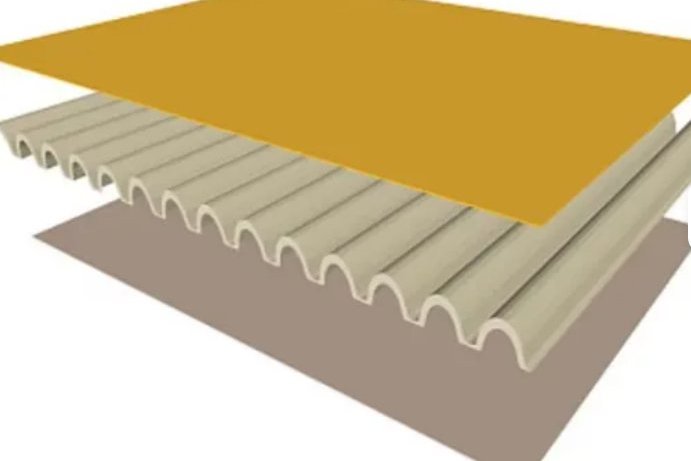
A blast-rated FRP panel is a sandwich. Two facesheets carry the bending stresses and a core holds them apart and carries the shear. The core does no bending work at all, which is why the depth of the panel matters far more than its total mass.
For a panel idealised as a simply supported strip, the flexural rigidity is dominated by the facesheets and can be written directly:
EI = Ef × 2 × [ b·tf3/12 + b·tf·(d/2)2 ]
where b is the strip width, tf the single facesheet thickness and d the centre-to-centre distance between the two facesheets. Because d appears squared, going from a 50 mm core to a 100 mm core multiplies the stiffness by roughly 3.7 for the same facesheets — and adds almost no mass. This is the most cost-effective move available in blast panel design, and it is the one clients most often resist because panel thickness is constrained by the opening it has to fit.
The facesheets themselves should be specified by their own standard, not by a generic "FRP" description. EN 13706-3 defines the pultruded profile grades; the E23 grade sets a minimum tensile modulus of 23 GPa and a minimum tensile strength of 240 MPa in the longitudinal direction. A balanced laminate made from stitched fabric and chopped-strand mat will typically sit below that in both properties. A design that assumes 240 MPa longitudinal but is manufactured from a mat-dominated layup is a design error that no amount of testing after the fact will fix.
Four things belong in the facesheet specification, and omitting any one of them leaves the blast performance undefined:
- Grade or layup schedule — either an EN 13706-3 grade call-out or an explicit ply schedule with fibre orientation and areal weight per ply;
- Reinforcement form — continuous roving, stitched fabric, chopped-strand mat or a hybrid, because the form sets both the achievable strength and the failure mode;
- Glass content by weight, verified per production batch rather than at first article only;
- Resin system and cure schedule, because post-cure and resin choice change both the modulus and the strain at failure.
6. Core Shear and the Facesheet–Core Bond: The Two Real Limits
Once a panel is bending, the core carries a shear stress that rises towards the supports. For a uniformly loaded simply supported strip, the average shear stress over the core depth is:
τ = w·L / (2·d)
with w the pressure and L the span in consistent units. The point to internalise is that this stress is independent of the facesheet thickness. Doubling the facesheets doubles the panel's bending strength and leaves the core shear demand untouched. So a designer who finds the core governing and responds by adding facesheet plies has made the panel heavier, more expensive, and no stronger — a mistake we see in roughly half of the third-party panel calculations that come across our desk.
The second limit is the facesheet-to-core joint. Under flexure the interface sees combined shear and peel, and the relevant coupon tests are:
- ASTM C273 — shear properties of the sandwich core, which gives the core shear strength and modulus used in the formula above;
- ASTM C297 — flatwise tensile strength of the sandwich construction, which measures the facesheet-to-core bond directly;
- ASTM C393 — core shear properties from a loaded sandwich beam, which is the test that catches a specimen whose bond is weaker than its core.
Adhesive film bonds and hand-laminated interfaces typically deliver flatwise tensile values in the 1.0–2.5 MPa band. That is the same order of magnitude as the core shear demand in a modest blast panel, which is why the bond must be qualified per production batch and not just at first article.
7. Anchorage, Connections and the Detachment Problem
In our experience the majority of real-world FRP panel failures under blast are anchorage failures. The panel survives; the fixings do not; the panel becomes a projectile. Three mechanisms account for most of it.
Bearing and tear-out at the bolt line. Pultruded FRP has a low transverse and bearing strength compared with steel, and blast loading reverses direction during the negative phase. A fixing designed for one-way wind pressure can be pulled out when the pressure reverses. Our dedicated guide to FRP structural bolted connections covers edge distance, bolt grades and bearing design in detail; the blast-specific addition is that you must check the negative-phase case, and that you should design the fixing for the dynamic reaction, not the static one.
Local crushing of the panel around the fixing. A bolt through a 50 mm sandwich panel will crush the core under load. Fixings must either pass through solid inserts, through a thickened solid-laminate edge strip, or through a through-bolted frame that bears on both facesheets. A fixing that bears on the inner facesheet alone will pull the inner skin off the core.
Load path into the supporting structure. The strongest panel in the world is limited by what it is bolted to. A dedicated steel frame is almost always cheaper than over-designing the panel, and it lets you define the reaction to the parent structure as a single number that the structural engineer can check.
Two further points are worth stating because they are cheap to get right and expensive to get wrong. First, keep the fixings outside the vented area wherever possible, so that the pressure rise does not load them in tension. Second, if the panel must be removable for maintenance, design the removal detail so that it cannot be partially re-installed — a panel held on four bolts of six is a projectile with a delayed fuse.
8. Where FRP Panels Act as Explosion Vents
A large share of FRP panel demand is not "blast resistance" at all; it is explosion venting of vessels, ducts, scrubbers and dust collectors. Here the panel is meant to open, and the design question is the required free vent area, not the panel strength.
NFPA 68 gives the vent area for a homogeneous dust deflagration at near-atmospheric initial pressure in the form:
A = a × V2/3 × KStb × Predc
with a = 0.000571 × exp(2·Pstat), b = 0.978 × exp(-0.105·Pstat) and c = -0.687 × exp(0.226·Pstat), where V is enclosure volume in m3, KSt the dust deflagration index in bar·m/s, Pred the reduced pressure after venting in bar-g and Pstat the nominal static burst pressure of the vent in bar-g. Working a 10 m3 FRP scrubber shell at KSt 150 bar·m/s, Pred 0.5 bar-g and Pstat 0.10 bar-g:
| Quantity | Value | Note |
|---|---|---|
| Enclosure volume V | 10 m3 | Include connected duct and hopper volume that stays open |
| Dust deflagration index KSt | 150 bar·m/s | From ASTM E1226 testing of your own dust |
| Reduced pressure Pred | 0.5 bar-g | Set below the vessel's own design pressure |
| Static burst pressure Pstat | 0.10 bar-g | Keep at least one third below the vessel rating |
| Required free vent area A | 0.67 m2 | NFPA 68 correlation as above |
| Same case, classic European VDI 3673 / EN 14491 form | 0.37 m2 | Pmax taken as 9 bar |
| NFPA 68 / European ratio | 1.82× | Quote the method your authority having jurisdiction accepts |
| Panel areal mass for the simple method | ≤ 40 kg/m2 | Above this, the mass correction in NFPA 68 8.3.4 or Annex G applies |
Two further corrections matter for FRP equipment because FRP vessels are often long and slender. For an elongated enclosure the classic European form adds area to allow for pressure piling:
ΔA = A × [-4.305·log10(Pred) + 0.758] × log10(H/D)
For our 10 m3 case this adds 0.42 m2 at L/D = 2, 0.83 m2 at L/D = 4 and 1.08 m2 at L/D = 6 — the vent area more than doubles at L/D = 6. FRP scrubbers, packed towers and long ducts regularly sit in that range, and this correction is routinely missed. Separately, where the vent panel mass exceeds 40 kg/m2, NFPA 68 requires the area to be increased for panel inertia.
Finally, an FRP vent panel is a pressure-relief device and should be treated as one: it needs a burst-pressure certificate with a tolerance band (typically ±10% on nominal), it needs to be inspected for corrosion and UV degradation on a defined interval, and it needs a documented safe discharge zone. Our FRP chemical storage tank safety guide covers containment, venting and bunding from the vessel side, and the two documents are meant to be read together.
9. Impact Resistance: Hard Body, Windborne Debris and Drop Weight
Impact duty splits into three families, and each has its own test basis.
Windborne debris. For external panels in cyclone and hurricane regions, the governing test is the missile impact plus cyclic pressure differential sequence of ASTM E1886 and ASTM E1996. This is a two-part test and both parts matter: the panel must survive the impact and then survive the cyclic pressure loading that follows, because the impact damages the panel and the cyclic load then finds the damage. A panel that passes the impact alone and fails the cycles is not compliant.
Localised hard-body impact. For walkway, handrail and structural panels exposed to dropped tools or falling material, the useful tests are instrumented or falling-dart methods — ASTM D5628 for a falling dart on flat rigid plastic specimens and ISO 6603-2 for instrumented puncture. For laminated and sandwich panels, drop-weight impact per ASTM D7136 followed by compression-after-impact per ASTM D7137 quantifies how much strength the panel loses once it has been hit — which is usually a far more useful number than the impact energy at which it perforates.
Ballistic duty. Where the requirement is small-arms protection, the applicable standards are EN 1522/EN 1523 for the FB1 to FB7 classes and UL 752 or NIJ 0108.01 for the US market. FRP alone is generally not a ballistic material; FRP panels in this duty are typically hybrid builds with an aramid or UHMWPE layer, and the panel should be certified as a complete assembly including its frame.
One impact figure is worth carrying in your head. Published drop-weight work on sandwich panels consistently shows that a panel which is undamaged by an impact and a panel which retains only a fraction of its flexural strength after the same impact can look identical from the outside. Impact damage in FRP is frequently invisible, which is why acceptance for impact-rated panels should be conditioned on post-impact residual strength testing rather than on a visual pass.
10. Test Methods and What a Test Report Has to Show
There are two families of blast test and they are not equivalent. A shock tube generates a planar pressure wave with a well-defined and repeatable reflected pressure and impulse, ideal for reproducible classification. An open-air arena test with a real charge produces the authentic pressure history, including the non-uniform loading and clearing effects that a shock tube cannot reproduce, but the parameters vary test to test. A specification should say which it wants.
ASTM F1642 is the common airblast test method for glazing and glazing systems, and its apparatus requirements are a useful proxy for what any panel test report should contain. The standard allows either a shock tube or an explosive charge; where a charge is used it must be hemispherical and its base elevated between 60 and 120 cm above the ground; the test frame must resist the load with deflections not exceeding L/360 along the lines of support; a witness area is set out behind the specimen with the floor 500 ± 50 mm below the subframe opening and the back wall 3.0 ± 0.15 m from the interior face; and the specimen is tested at an ambient of 24 ± 11 °C. Test facilities work in the 35–700 kPa range.
The hazard rating itself comes from the post-test debris location. ASTM F1642 defines tiers running from No Break, through No Hazard and Minimal Hazard, then Very Low, Low and Medium Hazard, up to High Hazard. ASTM F2912 is the specification that turns those ratings into installed-system requirements including frame anchorage and glazing bite, and ASTM F2248 provides the equivalent 3-second duration design load that lets a designer size a laminate against ASTM E1300 without a full dynamic analysis.
| Standard | Scope | Test type | Output |
|---|---|---|---|
| ASTM F1642 | Glazing and glazing systems under airblast | Shock tube or arena | Hazard rating tier |
| ASTM F2912 | Installed glazed assembly performance | Specification, uses F1642 data | Assembly acceptance criteria |
| ASTM F2248 | Laminated glazing design | Equivalent 3-second load | Design load for static sizing |
| ASTM F2927 | Door systems under airblast | Mechanical or explosive | Operability categories |
| EN 13123-1 / EN 13124-1 | Windows, doors, shutters and curtain walling | Shock tube | EPR1–EPR4 with S/NS suffix |
| EN 13123-2 / EN 13124-2 | Same assemblies | Open-air range test | EXR1–EXR5 with S/NS suffix |
| ISO 16933 / ISO 16934 | Explosion-resistant security glazing | Arena / shock tube | Hazard class with EXV prefix |
| UFC 3-340-02 | Structures resisting accidental explosions | Design criteria | SDOF response limits, DIF values |
| ASCE/SEI 59-22 | Blast protection of buildings | Design criteria | Levels of protection LOP I–IV |
| UFC 4-010-01 | DoD minimum antiterrorism standards | Design criteria | Standoff distances and hazard limits |
One structural change in this field deserves flagging to anyone writing a specification today. The 2022 edition of ASCE/SEI 59-22 added sections for composite construction, including provisions specifically for fibre-reinforced polymer composite members, alongside a simplified fragmentation assessment and updated glazing analysis methods. An FRP blast panel specified for a building project now has a recognised home in the standard, which was not the case in the 2011 edition. If a consultant tells you FRP cannot be treated as a blast-resistant material because the codes only cover steel and concrete, that statement was true in 2011 and is not true now.
The corresponding performance framework in ASCE 59-22 is expressed as four Levels of Protection, and they are expressed in terms of damage to the structure, damage to components and glazing performance — not in terms of a pressure number:
| Level of Protection | Structural damage | Component damage | Glazing performance |
|---|---|---|---|
| LOP I (very low) | Potential near-collapse | Hazardous | Low hazard |
| LOP II (low) | Unrepairable | Severe | Very low hazard |
| LOP III (medium) | Repairable | Moderate | Minimal hazard |
| LOP IV (high) | Minor | Minor | No fracture |
11. Worked Example: Rating a 1.2 m × 1.0 m Sacrificial Panel
The following example shows how the checks above combine, and why a pressure-only rating is not enough. The panel is a sandwich build with two 4 mm GFRP facesheets on a 50 mm core, spanning 1.2 m simply supported on two edges and treated as a one-way strip 1.0 m wide. The stated assumptions are: facesheet modulus 20 GPa, core shear modulus 30 MPa, facesheet design tensile strength 200 MPa (below the EN 13706 E23 minimum, which is appropriate for a stitched-fabric laminate), core design shear strength 1.2 MPa, laminate density 1,800 kg/m3 and core density 80 kg/m3. These are illustrative values and a project design must use coupon data.
| Quantity | Value | Where it comes from |
|---|---|---|
| Facesheet spacing d | 54 mm | 50 mm core + 4 mm facesheet |
| Second moment of area of the two facesheets | 5,842,667 mm4 per m width | Parallel-axis of two 4 mm skins |
| Panel areal mass | 18.40 kg/m2 | 2 × 4 mm × 1,800 + 50 mm × 80 |
| Panel mass / equivalent SDOF mass | 22.08 kg / 17.22 kg | KLM = 0.78, simply supported |
| Strip stiffness | 5,193 N/mm | 384·EI / (5L3) |
| Natural period Tn | 11.44 ms | 2π√(Me/Ke) |
With Tn = 11.44 ms, the same panel is dynamic for a 2–20 ms pulse and quasi-static only for durations above about 34 ms. A 20 ms deflagration gives td/Tn = 1.75, firmly in the dynamic regime, so a static check alone would be wrong in either direction depending on which limit it hits.
Now the two limit states, both referred to the same uniform pressure w on the panel:
| Limit state | Resistance Rm | Deflection at Rm | Support rotation | Comment |
|---|---|---|---|---|
| Facesheet tensile rupture | 240 kPa (2.40 bar) | 82.1 mm (L/14.6) | 7.79° | Would sit between EPR3 and EPR4 on pressure alone |
| Core shear at τ = 1.2 MPa | 108 kPa (1.08 bar) | 37.0 mm (L/32.5) | 3.52° | Governs; 2.22× lower than the facesheet value |
The core governs by a factor of 2.22. At the facesheet capacity the core would already be carrying 2.67 MPa, more than twice its 1.20 MPa allowable. Note also that the rotation implied by the facesheet capacity, 7.79°, already exceeds the 6° design support rotation that UFC 3-340-02 sets for ductile reinforced concrete in flexure — a further reminder that the concrete criterion is not a safe stand-in for a brittle FRP check.
Finally, convert both limit states to impulse capacity. For an SDOF system the impulsive asymptote is:
i = √(2 · Me · U) with U = 0.5 · Ke · δ2
| Referred to | Resistance | Deflection | Strain energy U | Impulse capacity i | Impulse per unit area |
|---|---|---|---|---|---|
| Facesheet rupture | 240.0 kPa | 82.1 mm | 17,512 J | 777 N·s | 647 kPa·ms |
| Core shear (governing) | 108.0 kPa | 37.0 mm | 3,546 J | 350 N·s | 291 kPa·ms |
Compare against the EN 13123-1 envelope. The panel's pressure capacity of 108 kPa comfortably clears the EPR2 minimum of 100 kPa. Its impulse capacity of 291 kPa·ms does not clear even the EPR1 minimum of 370 kPa·ms. Since a class is only awarded when both the minimum peak reflected pressure and the minimum positive-phase impulse are achieved, this panel cannot legitimately be described as EPR1 or EPR2 on the strength of its pressure number. That single comparison is the practical answer to the question this article opened with: pressure-only ratings on light FRP panels are almost always optimistic, because the panel is impulse-limited before it is pressure-limited.
The design response, in order of cost-effectiveness, is to shorten the span, deepen the core, or stiffen the core. Shortening the 1.2 m span raises the quasi-static resistance and the impulse capacity simultaneously; deepening the core does the same through d2; and replacing a soft foam core with a denser foam or a reinforced honeycomb lifts the governing shear strength directly. Adding facesheet plies is the last option, not the first, because it does not change the core shear demand at all.
Ranked by the improvement each delivers per kilogram added, and taking the worked example above as the baseline:
- Reduce the span. Highest return, because resistance scales with 1/L2 and stiffness with 1/L3. Add intermediate supports or a divider rail rather than thickening the panel.
- Deepen the core. Stiffness rises with d2 for almost no added mass, and the core shear demand per unit load falls as 1/d. Cost is thickness, not weight.
- Stiffen or strengthen the core. Directly raises the governing shear capacity. Move from a soft foam to a denser foam or a reinforced honeycomb, and confirm the change with ASTM C273 data.
- Improve the bond. Switch from a hand-laminated interface to a controlled adhesive film and qualify it with ASTM C297 per batch.
- Add facesheet plies. Last resort. It raises the bending capacity but leaves the core shear demand untouched, so it does nothing for the limit state that usually governs.
12. Specification and Incoming-Inspection Checklist
The following is the checklist we ask our own engineers to complete before an FRP blast or impact panel is released for manufacture. It is also a reasonable basis for a purchase specification.
| # | Item | Acceptance evidence |
|---|---|---|
| 1 | Threat definition: peak pressure, impulse, duration, or charge mass and standoff | Signed design basis document; a pressure-only statement is rejected |
| 2 | Target class and test route | Named class with S or NS suffix and the standard part, e.g. EN 13123-1 EPR2/NS |
| 3 | Target Level of Protection where the project uses ASCE 59-22 | LOP I–IV stated, with structural, component and glazing performance objectives |
| 4 | Load regime check | Calculated Tn and td/Tn, with the regime stated |
| 5 | Facesheet material grade | EN 13706-3 grade, or coupon tensile modulus and strength per batch |
| 6 | Governing limit state identified | Explicit core shear and flatwise bond check, not facesheet bending only |
| 7 | Core data | ASTM C273 shear strength and modulus, ASTM C297 flatwise tensile, on production laminate |
| 8 | Anchorage design | Dynamic reaction, negative-phase case, inserts or solid edge strip, through-bolted frame |
| 9 | Vent area where applicable | Calculation to the accepted method, with elongated-enclosure and panel-mass corrections |
| 10 | Burst pressure tolerance | Certificate with tolerance band, typically ±10% on nominal Pstat |
| 11 | Impact duty | Test method named (ASTM E1886/E1996, D5628, D7136/D7137, ISO 6603-2) plus residual strength |
| 12 | Test report content | Pressure–time traces from all transducers, high-speed video, post-test debris mapping |
| 13 | In-service inspection | Interval, corrosion and UV criteria, replacement trigger, documented safe discharge zone |
| 14 | Traceability | Resin batch, glass batch, core batch and layup record retained per panel serial |
Two of these items are the ones most often missing and the two that most often cause a problem later. Item 6, because a facesheet-only calculation routinely overstates a light panel's capacity by a factor of two or more, and item 12, because a test report that gives a single pass/fail verdict without the pressure–time traces cannot be used to extend the rating to a different threat, and you will be asked to do exactly that.
The deeper point is that an FRP panel is a system, not a sheet. Facesheets, core, bond, fixings, frame and supporting structure all participate, and the weakest of them sets the rating. Where the panel also forms part of a vessel or duct, the shell, stiffeners and supports have to be designed together with it — the approach in our FRP duct and hood fabrication guide applies directly, and for a panel that also has to contain a pressure boundary the relevant frame of reference is the one set out in our guide to FRP vessels under ASME Section X and RTP-1.
Ordering Blast-Rated and Impact-Rated FRP Panels
Henan HuanGang manufactures pultruded and sandwich-build FRP panels, FRP honeycomb sandwich panels for structural and protective duty, and the moulded FRP grating and walkway decks that usually sit behind them on an access platform. We also build the FRP duct and shell sections that these panels close, and the pultruded structural profiles for the supporting frames.
If you send us the threat definition from item 1 of the checklist above — peak pressure and impulse, or charge mass and standoff — together with the opening size and the surrounding structure, we will come back with a panel build, the governing limit state, an indicative class, and the fixing arrangement. If you only have a pressure figure, tell us that, and we will derive the impulse envelope that goes with it before quoting, because that is the number that will decide whether the panel works.
Related reading: FRP structural adhesive bonding for the joint design behind item 7, FRP sandwich panel selection for the core choice, FRP tank and vessel acoustic emission testing for in-service structural assessment, and FRP grating fire resistance if the panel also sits in a fire-exposed or fire-rated location.
Need help selecting FRP products?
Our engineers answer technical questions free of charge.
Ask an Engineer on WhatsApp