
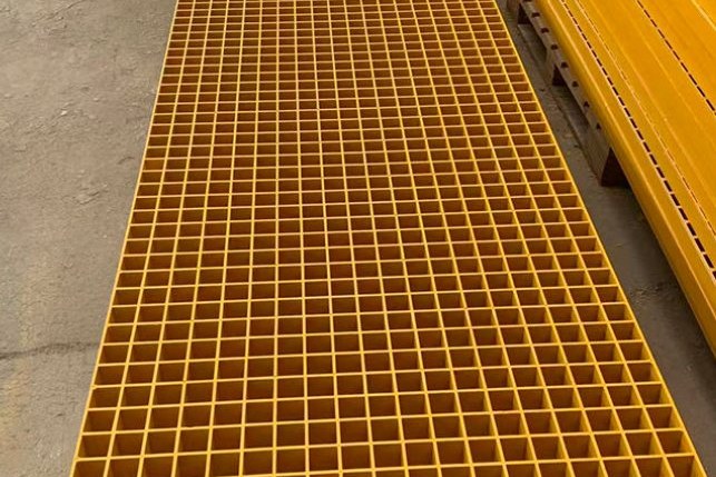
A dry dock is the least forgiving place in a shipyard to put a light composite walking surface. The grating is not just a floor: it is the surface that receives dropped steel, the surface that sits under a blast hose for days at a time, the surface that gets welded over, and the surface that men and women in blasting hoods have to walk on when it is wet, oily and covered in spent grit. Everything that damages FRP walking surfaces is concentrated within a few metres of the dock floor.
This guide sets out what the relevant standards actually require - ASTM F3059 above all, because it is the only FRP grating specification written for marine construction and shipbuilding - then works through the four loads that a shipyard applies: impact, slip, abrasive blasting, and hot work. The numbers come from a calculation script so the arithmetic can be checked, and the practical anchors are the panels and profiles we supply, such as our moulded FRP grating for walkways and floors.
1. Why a Shipyard Is Not an Offshore Platform
Offshore and marine composites are usually discussed as one subject, but the duty differs in four ways that change the specification.
- Impact is vertical and heavy. Platforms drop tools. Yards drop structural steel, keel blocks, chain, and plate offcuts onto the deck. The design case is a mass an order of magnitude larger than a spanner.
- Abrasive blasting is continuous. Blast media is not a splash exposure; it is a high-velocity stream aimed at steel for hours, with the FRP walkway in the blast envelope. Blasting removes resin from FRP if it is not masked.
- Hot work is routine. Welding and cutting happen on and around the walkway, which is an organic material.
- The floor is wet, oily and gritty at the same time, and it drains slowly because the dock floor is flat. Slip resistance is the dominant day-to-day hazard, not corrosion.
Corrosion, the usual reason FRP is specified at all, is almost a solved problem in this environment. The hard part is mechanical and procedural.
2. What ASTM F3059 Actually Requires
ASTM F3059, Standard Specification for Fiber-Reinforced Polymer (FRP) Gratings Used in Marine Construction and Shipbuilding, exists to let an FRP grating be considered equivalent to a steel grating rated for a maximum load of 94 lbf/ft² (4.5 kN/m²). It is written for gratings installed aboard vessels - machinery spaces, cargo holds and tanks, open decks - but because it is the only FRP grating specification tied to marine duty, shipowners, yards and class surveyors routinely adopt it as the acceptance basis for shoreside dock walkways as well. Two scope limits are worth reading before you cite it: it does not address the ability of the grating to support moving or stationary equipment during or after a fire, and it covers fire exposure based on the E119 furnace test only - not hydrocarbon pool or jet fires.
The test matrix it imposes is broad, and most of it is not about strength.
| Clause | Requirement | Value |
|---|---|---|
| §3.1.9 | Qualified span - the span used in the preload and post-load fire tests | Minimum 44 in. (1,120 mm) |
| §8.1.2 | Minimum uniform design load for the grating, safety factor included | 150 lb/ft² (7.2 kN/m²) |
| §8.1.3 | Maximum mid-span deflection at the qualified span | 0.25 in. (6.35 mm) |
| §9.1 | Assembled grating flexural strength, three-point bending, average of five specimens cut from three panels | 50,000 psi (345 MPa) minimum |
| §10 | Wheel loading: 6 in. × 2 in. hard rubber wheel, minimum 75 Shore A, loaded to 1,000 lb (454 kg), travelling perpendicular to the bearing bars at mid-span | 500 cycles (1,000 passes); no visible cracking, height loss not more than 0.03 in. (0.8 mm) |
| §11 | Assembled panel impact: steel impactor, impact area 120 in.² (775 cm²), dropped from a free-fall height of not less than 36 in. (91 cm) | 12,000 in.-lb of kinetic energy; retained flexural strength and stiffness (EI at L/50) at least 90 % of the control panel |
| §12 | Skid resistance per ASTM D2047 (James machine, dry leather) | Average coefficient of friction greater than 0.75 |
| §13 | Abrasion per ASTM D4060 with H-22 wheels, tested on the standard sample and on a UV-exposed sample | At least 1,200 cycles to wear through the grit to the substrate |
| §14 | UV exposure per ASTM D4329 | At least 720 h, then no breaks, cracks, blistering, delamination or exposed fibre |
| §15 | Salt spray per ASTM B117 | 7 days, then the panel must still meet the §9.1 flexural requirement |
| §16 | Surface flammability per ASTM E84, tested from both sides, with and without coatings | Flame spread index ≤ 20, smoke developed index ≤ 450 |
Three items in that table deserve to be used commercially rather than just quoted.
The deflection limit has a crossover. The absolute cap of 0.25 in. equals 6.35 mm, which is L/200 at a span of exactly 1,270 mm. Below that span the proportional rule L/200 is stricter than the absolute cap; above it the absolute cap governs. Both results are shown below.
| Span | L/200 | Absolute cap (0.25 in.) | Governing limit |
|---|---|---|---|
| 1,120 mm (minimum qualified span) | 5.60 mm | 6.35 mm | 5.60 mm - L/200 |
| 1,270 mm | 6.35 mm | 6.35 mm | 6.35 mm - tie |
| 1,500 mm | 7.50 mm | 6.35 mm | 6.35 mm - absolute cap |
| 1,800 mm | 9.00 mm | 6.35 mm | 6.35 mm - absolute cap |
A supplier quoting only "L/200" at a 1,800 mm span is therefore claiming roughly 42 % more deflection than the specification allows. Ask which criterion the published load table uses.
The wheel test is not a pedestrian test. A 1,000 lb load on a 6 in. wheel with a contact band of roughly 1 in. gives a bearing pressure of the order of 1,150 kPa on an assumed 152 mm × 25 mm patch. A 100 kg worker standing on one 200 mm × 200 mm footprint applies about 25 kPa. The wheel test is close to fifty times the pressure of the person it is supposed to represent - it is a test for trolley traffic and dropped-load points, not for walkways.
There is a unit conflict inside the impact clause. Clause 11.4.2 states the impact energy as 12,000 in.-lb, and gives the SI equivalent as 68,520 mm-N. Those two figures do not agree: 12,000 in.-lb is about 1,356 N·m, roughly 20 times the printed SI value, which corresponds instead to about 68.5 J. Clause 1.5 of the standard states that the inch-pound values are the standard and the SI conversions are for information only, so the governing requirement is the severe one - and at the 36 in. drop height it implies a falling mass of about 151 kg (333 lb). This is exactly the kind of ambiguity that ends up in a purchase specification as a single number; ask the manufacturer for the raw impact test report, not the summary line.
3. Fire Integrity: L0, L3, L2 and L1
F3059 handles fire in two parts. Surface flammability is the E84 test with a flame spread index of 20 or less and a smoke developed index of 450 or less. Structural fire integrity is a furnace test per E119, run for 60 minutes, with a preload and a post-exposure load sequence.
The furnace procedure, in the order it is applied: specimens are conditioned for at least 24 h at 23 ± 2.8 °C and 50 ± 5 % relative humidity and tested without coatings; the preload specimen carries a static load of 88 lbf (391 N) applied through a sand-filled container with a 1 ft² base at mid-span, and the time at which its vertical deflection exceeds L/10 is recorded; distributed load is then applied in increments of not more than 44 lbf (196 N) up to 94 lbf/ft² (4.5 kN/m²).
| Level | Test sequence after the furnace exposure | Acceptance | Typical service intent |
|---|---|---|---|
| L0 | No structural fire integrity test; E84 only | Flame spread index ≤ 20, smoke developed index ≤ 450 | Personnel walkways, catwalks and access areas in cargo holds and tanks |
| L3 | One post-load specimen, centre load test | Preload specimen does not deflect more than L/10 in the first 18 minutes; unloaded specimens do not collapse; centre load sustained for 15 minutes | Egress routes and access for firefighting, emergency operations or rescue after a very limited fire not likely to involve flammable liquids |
| L2 | Centre load test followed by the uniform load test | L3 plus the 94 lbf/ft² uniform load held for 15 minutes | Areas where personnel may need to assemble after a fire, including temporary safe refuge and lifeboat embarkation stations |
| L1 | Centre load, uniform load, E695 impact, then uniform load again - applied to all three post-load specimens | L2 on every specimen, plus the impact test | Escape routes and areas where access for firefighting, emergency operation or rescue is needed after a significant fire |
The L1 impact step uses ASTM E695 with the span set 203 mm less than the pretest specimen length and a lead shot bag of not less than 88 lb (40 kg) dropped from a minimum height of 200 cm - roughly 785 J into a panel that has just spent an hour in a furnace. If you want a single number to explain why L1 grating costs more than L0 grating, that is it.
The standard also maps levels to locations aboard a vessel. The pattern is not intuitive: machinery-space escape routes and firefighting access require L1A; other machinery-space walkways require L3; cargo pump rooms require L1 across the board; cargo tanks, fuel oil tanks, ballast tanks and cofferdams require only L0; and accommodation, service and control spaces are not permitted to use FRP grating at all. For a shoreside dry dock or yard walkway, the vessel location table does not apply - the yard's own fire regime and the insurer's rules govern - but the levels themselves are a useful vocabulary for stating how much post-fire capability you are actually buying.
One more clause to carry into a purchase order: each grating must be permanently marked with the brand and its fire rating (L1, L2, L3 or L0), and with the approval number where one applies. If the delivered panels are unmarked, the fire claim is unverifiable at handover.
4. Impact: Designing for the Things That Actually Fall
The yard's real loads are heavier than a specification table suggests. Using kinetic energy as the common currency:
| Dropped object | Mass | Fall height | Impact energy |
|---|---|---|---|
| Hand tool | 5 kg | 3.0 m | 147 J |
| Tool box | 12 kg | 2.5 m | 294 J |
| Steel plate offcut | 25 kg | 2.0 m | 490 J |
| Keel block or chain section | 100 kg | 1.5 m | 1,472 J |
Compare those with the F3059 impact requirement of the order of 1.36 kJ and the picture is clearer than any datasheet: the standard's impact test is calibrated to survive a dropped tool and a heavy shock load, and it is not a licence to hang a keel block over a grating deck. Nor does the test tell you what happens at the support. The impact panel is simply supported at the qualified span and held down with the manufacturer's clips or a 25 mm wide strap; in service, an unrestrained panel can walk off its bearings under repeated impact long before the laminate is damaged.
Moulded and pultruded grating behave differently under this load, and the choice should follow the load path rather than habit:
- Moulded grating is produced in one operation, so bearing bars and cross bars cure as an interlocked mesh. With roughly 35 % glass by weight it has lower absolute stiffness than pultruded material, but the mesh shares load in both directions and absorbs point impact well because the resin content is high.
- Pultruded grating is assembled from individually pultruded bearing bars locked by cross rods, with continuous fibre along each bar. It is stiff and strong along the bar, much weaker across it, and it spans further - which is why it wins on wide support spacing and loses on point impact and on cutting.
For a dry dock walkway, the impact case usually decides: use moulded grating with a grit top where objects fall, and reserve pultruded grating for long-span staging and framing where the load path is known and the drop risk has been engineered out by a catch deck or a protection layer.
5. Slip Resistance on a Wet, Oily, Grit-Covered Deck
There are three slip test systems in common use, they are not interchangeable, and a specification that names the wrong one for a dock floor is worse than no requirement at all.
| System | Test condition | Scale | Where it belongs |
|---|---|---|---|
| DIN 51130 (now inside the EN 16165 framework) | Shod operator on an oiled, tilting ramp | R9 6-10° · R10 10-19° · R11 19-27° · R12 27-35° · R13 above 35° | The correct language for a dock floor, blasting bay or oily engine space |
| ANSI A326.3 | Wet surface, BOT-3000E tribometer, dynamic coefficient of friction | Wet DCOF of at least 0.42 for level interior spaces expected to be walked on when wet; higher categories for exterior, ramp and oil-exposed areas | North American specification language for level interior wet areas - a minimum, not an industrial standard |
| EN 16165 Annex C / ASTM E303 | Pendulum on dry or wet surface | Values above about 36 indicate low slip potential | Survey work and verification on installed surfaces |
Two points of discipline here. First, R-ratings and DCOF cannot be converted: the DIN test uses oiled surfaces and a shod walker, the ANSI test a wet surface and a sliding sensor, and the pass criteria are different. If a buyer asks for DCOF ≥ 0.42, answering "R11" does not answer the question. Second, a DCOF of 0.42 corresponds by simple trigonometry to a ramp angle of about 22.8°, which lands in the middle of the R11 band. That is a useful orientation, and it also shows how low the bar is: an R11-equivalent floor is not what an oily dry dock needs. Specify R12 or R13 for docking bays and blasting areas.
Then notice what F3059 actually requires: a coefficient of friction greater than 0.75 measured to ASTM D2047 with the James machine under dry leather conditions. That is a dry test. It is not evidence of wet or oily performance, and it should never be offered as such. Use it as a quality gate on the grit bond, and use the ramp or pendulum test for the wet, contaminated condition that the dock floor actually presents.
The slip surface degrades from the top down, and the mechanism is worth stating: grit-top grating relies on abrasive particles bonded into the resin. Oil, paint overspray, dust and fine grit blind the particles; the F3059 §13 requirement of at least 1,200 Taber cycles to wear through the grit sets a floor for mechanical durability, but it does not stop contamination. A dock walkway needs a cleaning regime matched to the paint shop's overspray, not a once-a-year wash.
6. Abrasive Blasting: The Yard Process That Damages FRP Most
Blasting is specified for steel and applied indiscriminately, and that is how FRP walkways get destroyed. The physics is simple: kinetic power in the abrasive stream scales with the square of particle velocity, and velocity scales with the square root of the pressure drop across the nozzle. Halving the gauge pressure cuts the velocity to 71 % and the energy delivered per unit of media roughly in half.
| Parameter | Steel hull / structure | FRP surface |
|---|---|---|
| Nozzle pressure | 90-100 psi (6.2-7 bar), up to 125 psi (8.6 bar) for heavy coating removal | 30-60 psi (2-4 bar); fine crushed glass 40/70 grade at 30-50 psi with a wide fan nozzle |
| Media | Copper slag, garnet, steel grit | Walnut shell (Mohs 3.0-3.5), plastic media, corn cob; not crushed glass at hull pressures |
| Impact angle | Varies with profile target | About 45° is the practical optimum for FRP; normal incidence digs in |
| Air quality | Dry | Dry and oil-free; oil contamination is carried into the resin |
| Standoff and dwell | Set for production rate | Set to minimise material removal from the FRP, and validated on a test patch |
Three specific hazards are worth writing into the method statement.
- Grit embedment. Abrasive particles can be driven into the resin. Embedded grit becomes a water path and an abrasion point, and it will telegraph through any coating applied afterwards.
- Fibre exposure and pinholes. Where the surface is over-blasted, resin is removed and glass fibres stand proud. Protruding fibres create pinholes in any subsequent coating, and exposed fibres are the start of the UV degradation cycle that F3059 §14 is written to screen out.
- Substrate deformation and surface cracking. Too-hard grit, too much pressure or too long a dwell produces surface cracks and distortion, which is a structural problem rather than a cosmetic one.
The cheap control is procedural: mask or blanket every FRP walkway, ladder and handrail in the blast envelope with plywood or heavy sheeting, and treat "spot-blast the grating to clean it" as prohibited. If blasting FRP is genuinely unavoidable - for example to prepare it for a coating - treat it as a coating-preparation operation: clean and degrease first, choose media softer than the matrix, hold the angle near 45° with dry oil-free air, run a test patch to fix standoff and pass speed, then remove all dust and protruding fibres before coating.
7. Hot Work, Fire Watch and the Fire Class You Ordered
The grating's fire rating and the yard's fire exposure are different things and they must not be matched by title. F3059's structural fire integrity levels qualify a grating for a location aboard a vessel. Ashore, EN 13501-1 classification, the yard's hot-work procedure and the insurer's requirements are what the walkway has to satisfy, and the vessel location table in F3059 does not transfer.
What does transfer is the underlying material behaviour and the practical controls:
- Specify a flame-retardant resin system - a brominated vinyl ester or an antimony-bearing vinyl ester - where the grating sits in a hot-work zone, and say so on the drawing rather than leaving it to the supplier's default.
- Keep the deck clear before hot work: grinding swarf, oily rags, paint tins and thinners are all part of the fuel inventory, and none of them belong on a walkway any day of the year.
- Use fire blankets below and around welding or burning, and issue a formal hot-work permit that names the grating as a protected item.
- Understand the material's actual fire behaviour. Thermosetting resin composites char rather than melt and do not drip, but polyester, vinyl ester and epoxy laminates still release heat and smoke. Phenolic laminates char to an insulating carbon layer and release substantially less heat per unit mass - the price is brittleness, lower elongation and harder fabrication.
Finally, do not confuse F3059's fire levels with rail-sector requirements such as the EN 45545-2 requirement sets. They are different regimes written for different vehicles and different fire scenarios, and a grating qualified to one is not automatically qualified to the other. Our note on EN 45545-2 requirements for grating in rail and metro stations sets out that boundary, and it is a useful reminder that fire claims have to be read against the standard they came from.
8. Access, Confined Spaces and Blast-Hood Work
Yard walkways are governed not only by structural specification but by access rules, and in the United States the shipyard standard 29 CFR 1915 sets dimensions that our industry routinely gets wrong because it designs to general-industry numbers instead.
| Requirement | Reference | Dimension |
|---|---|---|
| Walking surface of the gangway, ramp or permanent stairway between a floating dry dock and the pier or bulkhead | 1915.75(a) | Not less than 20 in. (508 mm) |
| Railing height on dry-dock and graving-dock access, including access to wing walls from the dock floor, and on wing-wall and graving-dock edges | 1915.75(b), (d) | Approximately 42 in. (1,067 mm) with a midrail; railing on permanent stairways approximately 30-34 in. (762-864 mm) |
| Railing height on vessel gangways | 1915.74(a)(2) | Minimum approximately 33 in. (838 mm) measured at the stanchion, with a midrail |
| Catwalks on the stiles of marine railways | 1915.75(g) | Not less than 20 in. (508 mm) wide, with a guardrail and midrail on at least one side |
| Work platform width in restricted quarters | 1915.77(d) | At least 20 in. (508 mm) wide |
| Fall protection trigger for work aloft | 1915.77(c) | More than 5 ft (1,524 mm) above a solid surface: scaffold or sloping ladder, or personal fall arrest |
| Means of access to a confined space in which work may generate a hazardous atmosphere | 1915.76(b)(1) | More than one, unless the structure makes it impracticable |
Two of those clauses have direct consequences for how grating is laid out. First, 1915.77(c) requires that employees whose vision is restricted by blasting hoods, welding helmets or burning goggles work from scaffolds rather than from ladders - so a walkway that is too narrow to allow a hooded operator to pass is a compliance problem, not just an ergonomic one. Second, a dock floor is a low-lying area, and chlorine and other dense gases collect there; confined-space entry and gas monitoring on a dock floor need to be part of the same method statement as the walkway layout.
Respirable crystalline silica completes the access picture, because abrasive blasting is the largest single source of it in a shipyard. The OSHA standard for general industry and maritime sets a permissible exposure limit of 50 µg/m³ as an 8-hour time-weighted average and an action level of 25 µg/m³. Blasting with a media that contains crystalline silica, without containment, ventilation and respiratory protection, is a health exposure that no amount of walkway specification will mitigate - specify a low-silica or silica-free media, wet or dustless blasting where the coating allows it, and containment that keeps the dust off the very walkways discussed here.
9. Insulating by Design: What FRP's Electrical Properties Buy and Cost
In a yard, FRP's non-conductivity is not a curiosity; it changes three real design problems.
- No galvanic couple. A composite grating under a steel structure introduces no dissimilar-metal couple, so no galvanic corrosion cell forms at the bearing points - which is often where a steel grating would fail first.
- No stray-current path. On a dock with impressed-current cathodic protection, or in a plant where stray currents circulate through grounded equipment, FRP walkways and platforms interrupt the path rather than carrying it. That is why composite grating is the traditional choice for cell-room and substation floors.
- No sparking on impact. There is no metal-on-metal contact, which matters for tank cleaning and for any area with a flammable atmosphere.
The cost side is the mirror image, and it has to be designed for rather than discovered on site:
- Anything that needs an electrical path - cathodic protection test points, a welding return, static bonding, lightning protection - has to be provided separately, with an irreversible or bolted connection to the steel structure.
- A composite walkway gives no fault current path for electrical continuity testing; if the yard's earthing philosophy assumes the walking surface is conductive, that assumption is wrong.
- Pultruded FRP's longitudinal coefficient of thermal expansion is a little lower than steel's, but the difference is small compared with a handrail or profile fixed at both ends. Fixings on long runs need slotted holes or movement joints regardless of material.
10. Inspection, Repair and Edge Sealing
FRP grating in a shipyard fails by a small number of recognisable mechanisms, and most of them are visible long before they are structural. A workable inspection regime follows the damage rather than the calendar.
| What is inspected | What to look for | Action |
|---|---|---|
| Grit surface | Grit loss, gloss or contamination that blinds the abrasive particles; measure it with a pendulum or ramp test in situ rather than by eye | Clean; if the grit is worn through, replace the panel rather than re-coating the top |
| Resin surface | Chalking, colour change, exposed fibre, whitening around cut edges | Exposed fibre means UV degradation has begun; clean, abrade and reseal |
| Cut edges | Any edge cut on site that has not been sealed with resin | Seal it. Unsealed cut edges are the single most common yard-side defect and the easiest to prevent |
| Embedded grit | Grit driven into the resin by blasting, often visible as dark speckling | Record it as a coating-adhesion risk; if it is widespread, the panel is degraded |
| Panels and clips | Panels walked off their bearings, missing clips, enlarged holes, cracking at fixings, corroded fasteners | Replace with 316 stainless or composite clips. The fastener is usually the first component to fail, and it is the cheapest |
| Joints between bars | Delamination or whitening at cross-rod joints on pultruded panels | Tap test; delaminated panels are replaced, not repaired |
| Support steel | Corrosion of the steel the grating bears on, and loss of bearing width | Restore bearing width before reinstating the panel |
Set intervals rather than a vague "as required": a visual pass monthly in the blasting and hot-work zones, a full survey annually with the results tabulated panel by panel, and a re-inspection after any event that involved a heavy drop, a fire, or blasting without masking. Record the panel identification, the defect, the date and the decision - because the second survey is where a trend becomes visible, and a trend is what justifies replacement before failure.
Repair follows the material's logic. Surface damage within the resin is repairable with resin putty after abrading back to sound laminate; structural damage is not. A cut edge is repaired by sealing. A delaminated bearing bar, a cracked panel across a support, or a panel that fails a tap test is replaced. And a panel whose grit has worn through in a walkway carrying traffic should be replaced rather than patched with a grit coating, because the F3059 durability criterion of 1,200 Taber cycles is a statement about the factory-bonded grit, not about anything applied in the field.
Related reading on this site: FRP grating and profiles on offshore and marine platforms covers the saltwater and fire integrity side of marine duty; reading FRP grating load tables explains how uniform and concentrated loads are reported; moulded versus pultruded grating goes deeper on the process comparison; grating fabrication and field cutting covers clip fixing and edge sealing on site; machining FRP grating and profiles gives the workshop parameters; stair tread slip resistance sets out the ASTM E303 and ramp-test background; grating and handrail condition assessment provides the defect grading framework; and grating in electrical substations explains the electrical design rules behind section 9. For the hardware itself, see our heavy-duty moulded grating for chemical and marine environments, the fire-resistant class 1 anti-slip walkway grating, our pultruded hollow walkway panels for long spans, and the pultruded handrail and stair profile system that frames them.
Need help selecting FRP products?
Our engineers answer technical questions free of charge.
Ask an Engineer on WhatsApp