
An aluminium melting furnace is usually specified as if it were a steel furnace with a lower set point, and that is the mistake that destroys linings. Molten aluminium at 750 degrees Celsius has a viscosity of about 1.04 millipascal seconds, which is almost exactly the viscosity of water at room temperature. It does not need to be hot to flow into a pore; it needs a pore. It also reduces silica, attacks ceramics chemically through the magnesium in the alloy, and carries fluoride fluxes that remove silica as a gas. Ceramic fibre is an excellent insulator for an aluminium furnace and a disastrous working lining in one, and the whole design problem is knowing precisely where the boundary lies. This guide sets out the attack mechanisms, the pore-size criterion that decides whether the metal gets in, the thermodynamics behind the low-silica rule, the heat transfer that sizes each layer, and the dry-out schedule that most relines get wrong.
1. An Aluminium Furnace Is Not Just a Hot Box
The temperatures are lower than in a steel or cement furnace, which is why designers reach for lightweight insulation, and that instinct is right for part of the furnace. But three properties make aluminium uniquely demanding on a lining.
- It wets and infiltrates. Its surface tension at 750 C is about 0.85 newtons per metre, and its contact angle on most refractories is between 90 and 130 degrees, which is non-wetting but not by a wide margin. Any pore larger than the threshold size is flooded by gravity alone.
- It is a reductant. Aluminium metal reduces silica to silicon, and the silicon goes into the melt. Magnesium in the alloy does the same thing more aggressively.
- It comes with fluxes. Chloride and fluoride salts, used for degassing and dross conditioning, attack the same silica-rich phases that hold a refractory together, and fluorine carries silica away as silicon tetrafluoride gas.
Add the mechanical environment, where charging scrap and tapping metal erode the hot face, and the lining in the metal contact zone is doing something much harder than simply holding heat at 750 C.
2. Where Fibre Belongs and Where It Must Never Go
The furnace is not one environment, it is five, and the boundary is the metal line. Above it the lining sees flame, hot gas and radiation; below it the lining sees liquid metal. Ceramic fibre belongs on the gas side and behind a dense working lining on the metal side. It must never be the surface the metal touches.
| Zone | What the hot face sees | Working lining | Where the fibre goes |
|---|---|---|---|
| Hearth | Metal, dross, charging impact | Non-wetting castable plus an anti-penetration layer | Cold-face backup only, behind rigid insulation |
| Lower wall, below the metal line | Metal, flux, thermal cycling at the bath line | Non-wetting castable, low silica, low porosity | Backup board behind insulating castable |
| Upper wall, above the metal line | Flame, hot gas, splash | Clay-bonded or low-cement castable | Fibre board as a backup layer |
| Suspended roof | Radiant heat, flame, no metal contact | Fibre module is acceptable as the hot face | The primary insulation, 200 to 300 mm of modules |
| Door and burner surrounds | Flame impingement, cycling, sealing | Castable at the burner block, fibre behind | Board, blanket, paper and rope for sealing |
The rule that comes out of this table is simple and worth stating plainly. On the roof and the upper walls, ceramic fibre is the best available material. At the metal line and below, ceramic fibre is a backup layer that must be protected by a dense, low-silica, low-porosity working lining, and the thickness of that working lining is a chemical wear allowance rather than a structural one.
3. The Four Attack Mechanisms
Lining failures in aluminium furnaces are usually described as corrosion, which hides four different mechanisms with four different countermeasures.
- Infiltration. Metal enters the open porosity by gravity and capillary action, solidifies on cooling, and on the next heat expands and spalls the surface. It is controlled by porosity and pore size, not by chemistry.
- Reduction. Aluminium and magnesium reduce the silica in the refractory. The refractory loses silica, gains alumina, becomes friable and bloats, and the melt gains silicon. It is controlled by the silica content of the working lining.
- Flux attack. Alkali and fluoride salts from the melt and from the atmosphere flux the silica-rich binder, forming low-melting liquids that dissolve the bond. It is controlled by the binder chemistry and by keeping the fluxes away from the lining.
- Erosion. Charging, tapping and dross raking remove the softened surface mechanically. It is controlled by strength at temperature and by careful operating practice.
A lining that fails in six weeks has usually failed by infiltration first, because the infiltrated zone is then exposed to reduction and flux attack over a vastly increased surface area. Stopping infiltration is therefore the highest-value design decision in the metal contact zone.
4. The Pore-Size Criterion for Metal Contact
Whether the metal enters a pore is decided by a competition between the metal head and the capillary threshold of the pore. For a non-wetting liquid, the threshold pressure below which the pore stays dry is two times the surface tension times the absolute cosine of the contact angle, divided by the pore radius. Setting that equal to the hydrostatic head gives the critical pore radius:
r critical = 2 sigma times the absolute cosine of theta, divided by rho g h. Any pore throat larger than this fills spontaneously, and any pore smaller than it stays dry. The head is the depth of metal below the surface, so the bath line region is the most exposed part of the wall.
| Metal head | Hydrostatic pressure | Critical pore at 105 degrees | At 120 degrees | At 150 degrees, coated |
|---|---|---|---|---|
| 0.10 m | 2.3 kPa | 190 micrometre | 367 micrometre | 635 micrometre |
| 0.25 m | 5.8 kPa | 76 micrometre | 147 micrometre | 254 micrometre |
| 0.50 m | 11.6 kPa | 38 micrometre | 73 micrometre | 127 micrometre |
| 1.00 m | 23.2 kPa | 19 micrometre | 37 micrometre | 64 micrometre |
| 1.50 m | 34.8 kPa | 13 micrometre | 24 micrometre | 42 micrometre |
A 90 degree contact angle gives no threshold at all: the metal enters by gravity through any pore it can reach. That is the behaviour of an oxidised, contaminated or flux-soaked surface, and it is why a lining that has been allowed to accumulate flux fails much faster than a clean one.
The practical pore sizes make the design rule unambiguous. A dense low-cement castable has pore throats in the range of one to twenty micrometres and is safe at any bath depth. A lightweight insulating castable has pores from one hundred to five hundred micrometres and will flood. Ceramic fibre, at twenty to two hundred micrometres, sits exactly in the dangerous band. For a 1.5 metre bath, a working lining needs to be denser than 24 micrometres of pore throat, and that is a specification you can write and a supplier can test.
5. Reduction: The Thermodynamics Behind the Low-Silica Rule
The reason low-silica working linings are specified is not folklore. Comparing standard free energies of oxide formation at the bath temperature settles it. Per mole of oxygen consumed, at 1,023 kelvin:
| Reaction | Standard Gibbs energy | Comment |
|---|---|---|
| Si plus O2 to SiO2 | minus 722,764 joules | The least stable of the three oxides present |
| Four thirds Al plus O2 to two thirds Al2O3 | minus 885,231 joules | Alumina is the more stable oxide |
| Two Mg plus O2 to two MgO | minus 980,967 joules | Magnesia is the most stable of the three |
Subtracting the silica line from the alumina line gives the exchange reaction four thirds Al plus SiO2 gives two thirds Al2O3 plus Si, at minus 162 kilojoules per mole of silica. Aluminium therefore does reduce silica at bath temperature, and it does so decisively. The equilibrium silicon activity works out at about 2 times 10 to the eighth, which is far above unity, meaning the reaction is not limited by silicon build-up in the melt at all: it proceeds until the silica is consumed.
Magnesium is worse. The same subtraction against the magnesia line gives minus 258 kilojoules per mole of silica, and aluminium alloys that contain magnesium attack a silica lining faster than any other common alloy. This is the reason a lining that performs acceptably on a 1xxx or 3xxx alloy can fail in a season on 5083 or 5182.
Fluorides add a second route that has nothing to do with oxygen. Silicon tetrafluoride is a gas at these temperatures, so silica is removed from the lining as vapour: each mole of silica leaves as 60 grams of SiO2 carried off by 76 grams of fluorine. That route destroys the refractory structure without any reduction at all, and it is the mechanism behind the pitting seen around flux injection points and dross ports.
6. The Silicon Budget: A Number for the Spec Sheet
The chemistry above converts into a specification figure that is easy to argue about with a supplier. Each kilogram of silica reduced consumes 0.600 kg of aluminium, produces 0.467 kg of silicon and leaves 1.133 kg of alumina behind. Applied to a 250 millimetre working lining, one square metre of wall contains:
| Working lining | Silica content | Mass per square metre | Silica available | Silicon available |
|---|---|---|---|---|
| Fireclay castable | 45 per cent | 550 kg | 247.5 kg | 115.5 kg |
| Low-cement castable | 30 per cent | 600 kg | 180.0 kg | 84.0 kg |
| High-alumina castable | 10 per cent | 725 kg | 72.5 kg | 33.8 kg |
| Bauxite with silicon nitride, non-wetting | 2 per cent | 725 kg | 14.5 kg | 6.8 kg |
| Tabular alumina castable | 0.1 per cent | 775 kg | 0.8 kg | 0.4 kg |
Those are the totals if the whole layer were consumed, which it never is. The useful version of the number is the contamination rate, which comes from the actual chemical wear rate. For a ten tonne holding furnace with fifteen square metres of wetted wall:
| Working lining | Wear rate | Silicon to the melt | Silicon pick-up | Time to reach 0.6 per cent Si |
|---|---|---|---|---|
| 45 per cent silica fireclay | 1 mm per month | 6.93 kg per month | 693 ppm per month | 8.7 months |
| 45 per cent silica fireclay | 5 mm per month | 34.65 kg per month | 3,465 ppm per month | 1.7 months |
| 30 per cent silica low-cement | 1 mm per month | 5.04 kg per month | 504 ppm per month | 11.9 months |
| 10 per cent silica high-alumina | 1 mm per month | 2.03 kg per month | 203 ppm per month | 29.6 months |
| 2 per cent silica non-wetting | 1 mm per month | 0.41 kg per month | 41 ppm per month | 147 months |
A 6061 melt tolerates 0.6 to 1.0 per cent silicon. A 5052 or a 3003 melt tolerates 0.25 to 0.6 per cent. The lining chemistry, and not the furnace design, decides which alloy a given furnace can hold, and that is why the alloy being cast belongs on the refractory specification.
7. Zone-by-Zone Heat Flux and Shell Temperature
The thermal design is a straightforward series calculation, but it has to be done with temperature-dependent conductivity and with the right hot-face boundary condition, because liquid metal couples to the lining far better than gas does. A metal contact surface coefficient of 1,500 watts per square metre kelvin is realistic; a gas and flame surface coefficient of 60 to 80 is realistic on a wall or roof. The exterior is taken as natural convection and radiation combined, at about 14.
| Zone | Hot face | Total thickness | Heat flux | Shell temperature | Touch safe |
|---|---|---|---|---|---|
| Hearth | 750 C metal | 500 mm | 640 W/m2 | 71 C | No |
| Lower wall, below the metal line | 750 C metal | 590 mm | 470 W/m2 | 59 C | Yes |
| Upper wall, above the metal line | 950 C gas | 590 mm | 536 W/m2 | 63 C | No |
| Suspended roof | 1,050 C gas | 450 mm | 752 W/m2 | 79 C | No |
| Door | 900 C gas | 320 mm | 947 W/m2 | 93 C | No |
Two results are worth noting. The lower wall, which carries the thickest and most expensive stack, is the coolest, and that is not an accident: the metal contact layer is dense and conductive, and the design compensates with a thicker insulating build-up behind it. And the door is the worst surface on the furnace in both flux and shell temperature, because it is thin, it cannot carry much insulation, and it is the one surface an operator actually touches. The hearth is also hotter at the shell than the lower wall despite a thinner stack, because the metal contact coefficient drives the flux up and the calcium silicate layer is thin.
8. What an Extra 50 mm of Fibre Buys
The roof is where adding fibre is cheapest and most effective, because there is no metal contact and the fibre can be the hot face. Taking the stack above and thickening the blanket layer while holding everything else constant gives a clear trade between insulation and shell temperature.
| Blanket thickness | Heat flux | Shell temperature | Castable to insulating interface |
|---|---|---|---|
| 50 mm | 752 W/m2 | 79 C | 910 C |
| 75 mm | 637 W/m2 | 71 C | 932 C |
| 100 mm | 553 W/m2 | 65 C | 948 C |
| 125 mm | 490 W/m2 | 60 C | 959 C |
| 150 mm | 441 W/m2 | 57 C | 969 C |
Note that thickening the cold-face fibre raises the temperature at the castable to insulating castable interface, because the same heat has to cross a larger temperature drop through a thinner effective hot-face stack. Cold-face fibre is not free: it moves the isotherms back into the working lining, and past a point that shortens the working lining's life. The correct target is a shell temperature at or below 60 degrees, which here needs 125 mm of blanket rather than 50.
The economics of the extra 50 millimetres are worth doing properly. On a 12 square metre roof running 7,000 hours a year with gas at 35.5 megajoules per cubic metre and a combustion efficiency of 0.85, going from 50 to 100 millimetres of blanket saves 199 watts per square metre, which is 2.38 kilowatts, or 16,691 kilowatt hours a year and 60.1 gigajoules a year of lining loss. That is 70.7 gigajoules of gas, about 1,991 cubic metres, worth roughly 697 US dollars a year. At 60 dollars per square metre supplied and fitted, the additional 50 millimetres costs 720 dollars and pays back in about twelve months. After that it is profit, and the shell is 14 degrees cooler into the bargain.
9. Coatings: What They Do and What They Cannot Do
Non-wetting coatings are the most oversold item in an aluminium furnace. They work, but they work within limits, and understanding those limits is the difference between a useful consumable and a disappointment.
A boron nitride wash applied as a 0.2 millimetre dry film at 1.9 grams per cubic centimetre puts 0.38 kilograms of solids on every square metre. At 40 dollars per kilogram of coating that is 15.20 dollars per square metre of coated surface, and at 90 dollars per kilogram it is 34.20 dollars. It works by raising the contact angle from about 120 to about 150 degrees, which raises the critical pore radius by a factor of 1.7. At a 0.5 metre metal head that moves the threshold from 73 to 127 micrometres, and at 1.5 metres from 24 to 42 micrometres. Useful, and not a substitute for a dense lining, because it only protects the pore mouths at the surface and it wears away.
| Coating | Maximum service temperature in air | Where it is used |
|---|---|---|
| Boron nitride | 900 C | Metal line, launders, transfer troughs, tap holes |
| Graphite or carbon wash | 600 C, oxidises in air | Transfer ladles, ingot moulds, skimmer blades |
| Alumina wash | 1,500 C | Burner blocks, flue, and anywhere above the metal |
| Zircon wash, silica free | 1,400 C | Tap holes, spouts, pouring lips |
Two rules govern application. The lining must be completely dry before the coating goes on, because painting an impermeable film over a wet surface traps water underneath and spalls the working face on the first fire. And the coating is a consumable, not a cure: budget to re-coat the metal line every tapping campaign and inspect it at every reline rather than assuming it is still there.
10. Dry-Out: The Water Balance That Sets the Schedule
Dry-out is the step that turns a good lining into a failed one, and it is almost always rationalised as a time problem when it is really a volume problem. Consider a 250 millimetre working lining at 2,400 kilograms per cubic metre placed with 6 per cent water. Per square metre, that is 600 kilograms of refractory carrying 36 kilograms of free water. At 100 degrees, 1 kilogram of water becomes 1,673 litres of steam, so the lining has to vent about 60 cubic metres of steam per square metre of surface. The energy involved, 93 megajoules per square metre or 25.9 kilowatt hours per square metre, is modest; the volume is not, and it has to escape through a lining whose permeability is at its lowest exactly when it is wettest.
An insulating castable is worse. At 30 per cent water by weight and 1,000 kilograms per cubic metre over 150 millimetres, there is 45 kilograms of water per square metre and 75 cubic metres of steam to shift, for 117 megajoules per square metre. Lightweight materials hold more water and release it more slowly.
| Material, first fire | Maximum ramp | Hold at 110 C | Time from 110 to 900 C | Total schedule |
|---|---|---|---|---|
| Dense castable | 25 C per hour | 24 hours | 31.6 hours | 55.6 hours |
| Insulating castable | 15 C per hour | 24 hours | 52.7 hours | 76.7 hours |
| Rammed or gunned | 20 C per hour | 24 hours | 39.5 hours | 63.5 hours |
| Fire brick | 30 C per hour | 12 hours | 26.3 hours | 38.3 hours |
| Ceramic fibre module | 50 C per hour | 4 hours | 15.8 hours | 19.8 hours |
The comparison is stark. A 250 millimetre castable wall needs 24 hours of curing plus roughly two and a half days of dry-out before it is anywhere near operating temperature, and the furnace is unavailable throughout. A fibre roof needs a shift. On a seven day reline, that difference is worth more than the fuel saved over the whole campaign, and it is the strongest operational argument for fibre above the metal line.
The hold at 110 degrees is not a formality. Hold until the shell stops steaming, not for a fixed clock time, and treat visible steam at the shell or at a joint as an instruction to stop the ramp rather than to continue it. Open every vent, damper and door before the first fire, and keep them open through the whole of the moisture release stage.
11. Shrinkage, Compression and Joint By-Pass
A ceramic fibre module is installed compressed, and the compression is the whole sealing mechanism. Take a 300 millimetre module installed at 15 per cent compression: the reserve is 45 millimetres. Service shrinkage of 3 per cent consumes 9 millimetres, and shell growth at 80 degrees consumes 0.2 millimetres, leaving 35.8 millimetres of reserve. That is why a module lining tolerates uneven burn-out and thermal cycling, and it is why the compression figure on the installation drawing matters more than the nominal thickness.
A flat board or blanket layer has no such reserve, and that changes the failure mode. If the fibre layer develops an open joint, the joint is not an insulation defect, it is a radiation window. Comparing one square metre of 50 millimetre fibre board with the same area interrupted by a 1.5 millimetre slit, with the faces at 500 and 100 degrees Celsius: radiation across the slit carries about 14,162 watts per square metre, against 912 watts per square metre through the board itself. The slit is 15.5 times more conductive than the material it punctures.
- Half a per cent of the area as slits adds 7.8 per cent to the total heat flux through the layer.
- One per cent as slits adds 15.5 per cent.
- Two per cent as slits adds 31.1 per cent.
- Five per cent as slits adds 77.6 per cent.
The conclusion is that joint quality beats thickness. A 100 millimetre board layer with open butt joints and no stagger performs worse than a 50 millimetre layer with tight, staggered, compression-filled joints. Specify the stagger pattern and the joint filling in the installation procedure, and inspect the joints before the layer behind them is covered up.
12. Heat Storage and the Cycling Penalty
Heat stored in the lining is paid for on every cold start, and the difference between a dense stack and a fibre stack is very large. Comparing one square metre of the castable roof stack with one square metre of a 300 millimetre fibre module roof, heated from 25 degrees to operating temperature, the castable stack stores about 714 megajoules per square metre and the fibre stack about 33 megajoules, a reduction of 95 per cent.
What that is worth depends entirely on how often the furnace starts. On a 12 square metre roof, a furnace that is shut down and cooled to ambient daily pays 2,453 gigajoules a year for that stored heat, which is worth roughly 28,448 US dollars in gas. A furnace with a weekend shutdown and 50 starts a year pays 409 gigajoules, worth about 4,741 US dollars. And a furnace that runs continuously through the week realises almost none of it, because the lining stays hot.
So heat storage is a decisive argument for fibre on a cycled melting furnace and a secondary one on a holding furnace. On a holding furnace the arguments that matter are heat flux and dry-out time instead, and both of those favour fibre as well, just less dramatically.
13. Launch Troughs, Launders and Transfer Ladles
The transfer path is where ceramic fibre does its least controversial work, because the fibre sits behind a dense working lining, never sees metal, and every watt it keeps in the trough is a watt the casting station does not have to put back. Take a trough 300 millimetres wide and 250 millimetres deep carrying metal at 740 degrees, with a build of 50 millimetres of non-wetting castable, 25 millimetres of anti-penetration board, 50 millimetres of ceramic fibre board and 25 millimetres of calcium silicate board.
| Configuration | Heat flux | Shell temperature | Loss per metre of trough | Metal temperature drop over 25 m at 30 t/h |
|---|---|---|---|---|
| 150 mm build, open top | 911 W/m2 | 90 C | 729 W/m | 2.0 C |
| Plus 75 mm blanket on a lid | 415 W/m2 | 55 C | 332 W/m | 0.9 C |
Covering the trough cuts the loss by more than half and takes the shell from 90 to 55 degrees, which is the difference between a surface that needs guarding and one that does not. The metal temperature drop falls from 2.0 to 0.9 degrees over a 25 metre run, which is small in absolute terms but is exactly the kind of uncontrolled variable that moves a casting out of its window on a cold morning. Stable, predictable trough loss is more valuable than low trough loss.
The same logic applies to the ladle lid, the dross pan and the flux hopper. Anywhere the metal is contained but not directly worked is a place where a fibre board behind a dense working lining pays for itself quietly.
14. Specification Checklist
An aluminium furnace lining specification that is written around temperature alone will fail. The following items are the minimum needed to specify the fibre package and the working lining together.
| Item | What to state | Why it matters |
|---|---|---|
| Alloy family | 1xxx, 3xxx, 5xxx, 6xxx, and magnesium content | Magnesium drives the reduction rate; a 5xxx melt needs a much better lining |
| Bath depth | Metal depth and metal line position | Sets the hydrostatic head and therefore the critical pore size |
| Flux practice | Flux type, quantity and where it is added | Fluorides remove silica as gas and attack the binder |
| Working lining | Silica content, alumina content, apparent porosity, pore size | Silica content sets the silicon pick-up; porosity sets infiltration |
| Fibre form by zone | Module, board, blanket, paper or rope, with thickness and density | Modules for roofs, boards behind dense linings, paper and rope for joints |
| Classification versus service temperature | Both, separately | Classification is not a service rating; design 100 to 200 degrees below it |
| Atmosphere | Oxidising, reducing or flux-laden | Reducing atmospheres attack metallic anchors above 800 C |
| Coating | Type, thickness, and who applies it after dry-out | A coating applied wet traps water and spalls the face |
| Dry-out | Ramp rate, hold temperature, hold criterion, venting | Determines whether the lining survives its first fire |
| Anchor system | Material, spacing, whether ceramic or metallic | Metallic anchors lose strength above 1,000 C and need ceramic cups |
The short version of the whole guide is that ceramic fibre is the right material for an aluminium furnace everywhere except the surface the metal touches. Above the metal line, use it as the hot face and enjoy the low conductivity, the low heat storage and the short dry-out. At and below the metal line, put 250 millimetres of dense, low-silica, low-porosity castable in front of it, coat what the metal will see, and treat the fibre behind as a backup layer that must never be exposed.
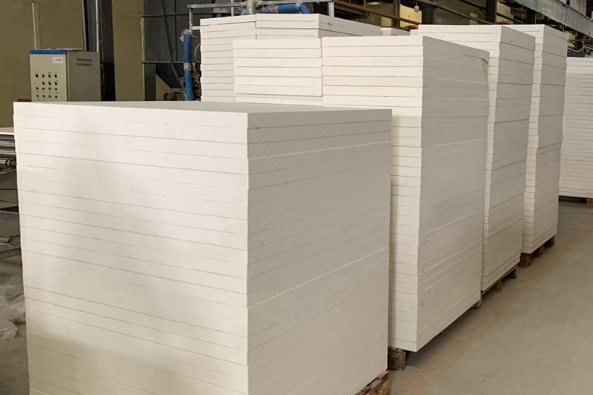
We supply silicon-alumina ceramic fibre in board, blanket, module and paper form across the 1,260, 1,430 and 1,600 degree grades, together with the anchors, the sealing materials and the anti-wetting coatings that a furnace lining package needs. Our aluminium silicate ceramic fibre board for furnaces is the backing layer that most aluminium furnace roofs and upper walls are built around, and we will happily review a lining drawing against the zone table above before it is ordered. Send us the alloy, the bath depth, the flux practice and the furnace drawing, and we will come back with a layer-by-layer build for each zone, the shell temperature to expect, and the dry-out schedule to follow.
Related reading: ceramic fibre blanket versus board versus module, ceramic fibre module installation and anchoring, calcium silicate board versus ceramic fibre, refractory materials selection, anchor systems for castable and fibre linings, castable mixing, curing and dry-out, high-alumina bricks by kiln zone, rock wool versus ceramic fibre in furnaces, ceramic fibre paper, textiles and expansion joint seals and passive cable fire protection.
Need help selecting FRP products?
Our engineers answer technical questions free of charge.
Ask an Engineer on WhatsApp